Clutch mechanism of electric pipette

A technology of clutch mechanism and pipette, which is applied in the field of pipette, can solve the problems of motor blocking, pipette stroke adjustment failure, etc., and achieve the effect of ensuring safe work

Pending Publication Date: 2020-07-14
SUZHOU SCHNITGERLAB ELECTRIC CO LTD
View PDF0 Cites 0 Cited by
  • Summary
  • Abstract
  • Description
  • Claims
  • Application Information

AI Technical Summary

Problems solved by technology

When the motor control fails, the screw will move forward in one direction. Once it reaches the limit position, the motor will be blocked, and eventually the pipetting stroke adjustment of the pipette will fail, and the pipetting operation will no longer be possible.

Method used


Image

  • Clutch mechanism of electric pipette
  • Clutch mechanism of electric pipette
  • Clutch mechanism of electric pipette

Examples


Embodiment Construction

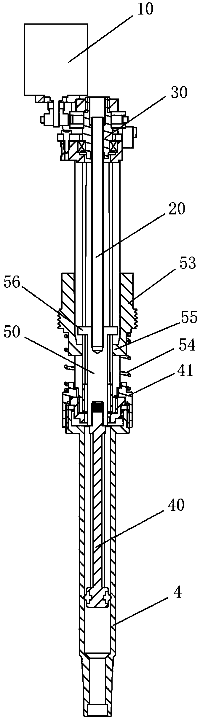
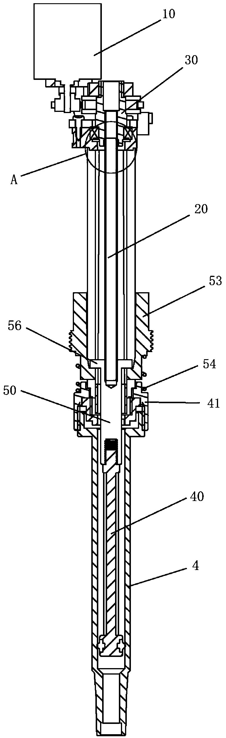
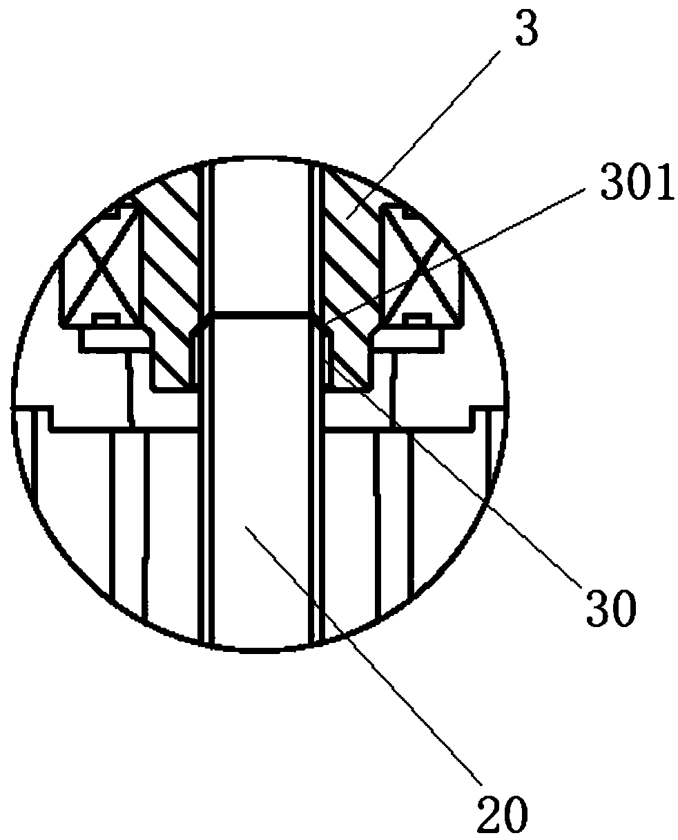
[0025] see Figure 1-5 , an electric pipette clutch mechanism, which includes a screw nut 3, a screw rod 20, a piston rod 40, the piston rod 40 is placed in the inner piston cylinder 4, and the screw nut 3 is driven by a drive motor 10 To or reverse rotation, the upper end of the screw rod 20 is connected with the internal thread of the screw nut 3, the lower end of the screw rod 20 is connected with the upper end of the piston rod 40, the lower end of the screw nut 3 The end is provided with a limit groove 30, the limit groove 30 is concentric with the internal thread of the screw nut 3, and the limit groove 30 is used to connect the external thread of the screw rod 20 with the screw rod. When the internal thread of the nut 3 is separated, the upper end of the screw rod 20 is restricted from deviating from the axis; the axial length of the screw rod 20 connected to the piston rod 40 is less than or equal to that between the bottom of the limiting groove 30 and the piston rod ...


PUM


Abstract

The invention discloses a clutch mechanism of an electric pipette. The clutch mechanism comprises a screw rod nut, a screw rod and a piston rod, the piston rod is arranged in a piston cylinder, the screw rod nut is driven by a driving motor to rotate in a forward and reverse direction, the upper end of the screw rod is connected with an inner thread of the screw rod nut, the lower end of the screwrod is connected with the upper end of the piston rod, a limiting groove is formed in the end part of the lower end of the screw rod nut, the limiting groove is coaxial with the inner thread of the screw rod nut, and the axial length of the screw rod connected with the piston rod is less than or equal to the distance between the bottom of the limiting groove and the bottom of the piston cylinder.According to the clutch mechanism of the electric pipette, when a motor is out of control or a piston is continuously driven to move downward, the situation that the piston rod abuts against the bottom of the piston cylinder and cause the motor stalling can be effectively avoided, and thus the safe and stable operation of the pipette is ensured.

Description

technical field [0001] The invention relates to the technical field of pipettes, in particular to an electric pipette clutch mechanism. Background technique [0002] At present, electric pipettes generally use a motor to drive the nut to rotate, and then drive the screw to move linearly in the nut to push and pull the piston for micro-operation. When the motor control fails, the screw will move forward in one direction. Once it reaches the limit position, the motor will be blocked, which will eventually cause the pipette stroke adjustment to fail, and the pipetting operation will no longer be possible. Contents of the invention [0003] Therefore, the technical problem to be solved by the present invention is to overcome the above-mentioned shortcomings existing in the existing electric pipette, and further provide a clutch mechanism for the electric pipette. [0004] To achieve the above object, the present invention adopts the following technical solutions: [0005] An...

Claims


Application Information

Patent Timeline
IPC IPC(8): F16D43/28
CPCF16D43/28
Inventor 张桂娣张翠郑雪凝
Owner SUZHOU SCHNITGERLAB ELECTRIC CO LTD
Why Eureka
Try Eureka