
Radiator

A radiator and heat source technology, applied in the direction of heat sinks, indirect heat exchangers, heat exchange equipment, etc., can solve the problems of insufficient heat exchange, low air velocity, and reliability of components, so as to enhance the heat dissipation efficiency, change the Air flow state, the effect of improving the air flow field

Pending Publication Date: 2020-07-14
GREE ELECTRIC APPLIANCES INC
View PDF0 Cites 0 Cited by
  • Summary
  • Abstract
  • Description
  • Claims
  • Application Information

AI Technical Summary

Problems solved by technology

[0003] The current heat dissipation methods include: using cooling fins to dissipate heat from heating components, or using a combination of fans and fins to dissipate heat, but due to the placement of fins and heating components and the wind field between the fins Influence, resulting in low heat dissipation efficiency of the radiator, laminar flow on the surface of the fins, low air flow rate, insufficient heat transfer, and continuous high-temperature operation of the heating module, which has a great impact on the use of equipment and has a greater impact on the reliability of components. big impact

Method used


Image

  • Radiator
  • Radiator
  • Radiator

Examples


Embodiment Construction

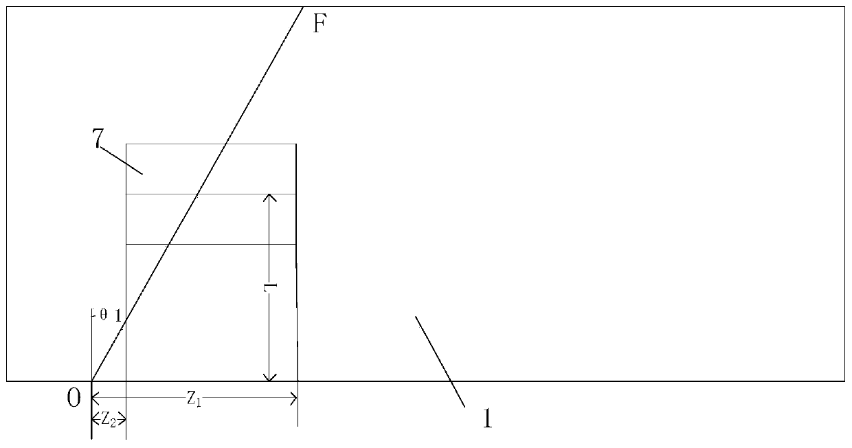
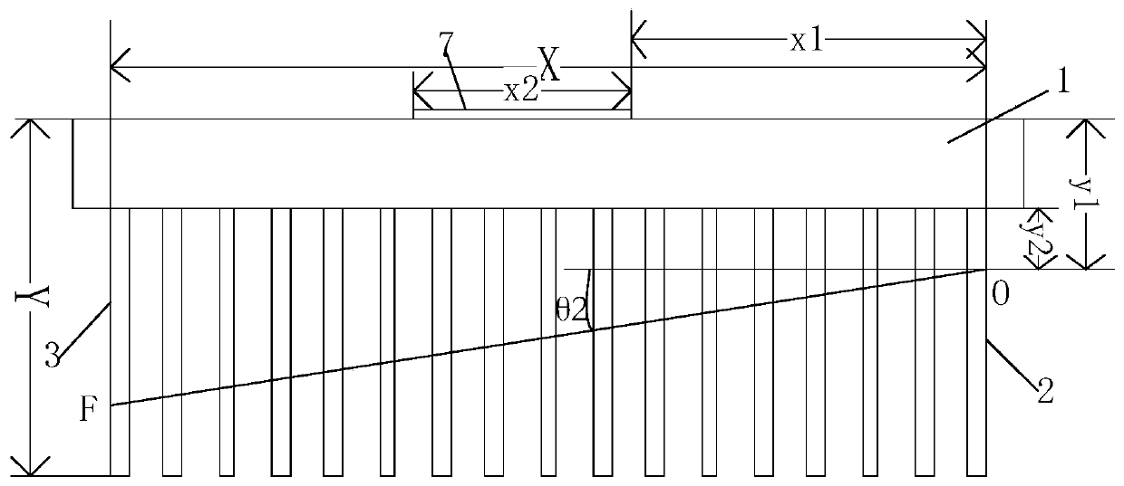
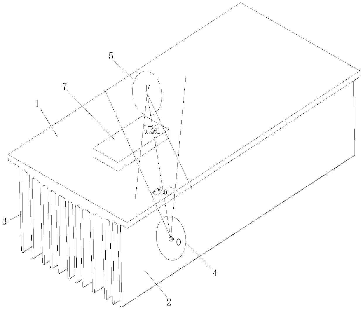
[0027] see in conjunction Figure 1 to Figure 4 As shown, according to the embodiment of the present application, the heat sink includes a substrate 1 and fins, a plurality of fins are arranged at intervals on the substrate 1, each of the fins is respectively provided with flow holes, and the fins It forms a preset angle with the direction of the airflow. Along the direction of the airflow, the fins include the first end fin 2 that first contacts the airflow and the end fin 3 that finally contacts the airflow. The flow hole on the fin 2 is the head flow hole 4, the flow hole located on the end fin 3 is the end flow hole 5, and the head flow hole 4 and the end flow hole The flow holes between 5 are the middle flow holes 6, and the middle flow holes 6 are all located on the central line OF connecting the head flow holes 4 and the end flow holes 5.

[0028] This application changes the air flow mode of the radiator, so that the direction of the air flow is not along the extensio...


PUM


Abstract

The invention provides a radiator. The radiator comprises a substrate (1) and fins, wherein the plurality of fins are arranged on the substrate (1) at intervals, an overflowing hole is formed in eachfin, a preset included angle is formed between each fin and the incoming direction of an air flow, the fins comprise a head-end fin (2) making contact with the air flow firstly and a tail-end fin (3)making contact with the air flow finally in the incoming direction of the airflow, the overflowing hole located at in the head-end fin (2) is a head-end overflowing hole (4), the overflowing hole located at in the tail-end fin (3) is a tail-end overflowing hole (5), the overflowing holes between the head-end overflowing hole (4) and the tail-end overflowing hole (5) are middle overflowing holes (6), and the middle overflowing holes (6) are all located in the center line of the head-end overflowing hole (4) and the tail-end overflowing hole (5). According to the radiator, the laminar flow stateof the surfaces of the fins of the radiator can be broken, air flow fields between the fins and around the fins are improved, and the radiating efficiency of a heat component is enhanced.

Description

technical field [0001] The present application relates to the technical field of heat dissipation, in particular to a heat sink. Background technique [0002] At present, due to the popularization of intelligence and integration, many electronic components generate a lot of heat, but they are concentrated and compactly placed on the same circuit board. In order to ensure the long-term reliability of components and ensure the normal operation of equipment, heat dissipation devices are added. is an effective method. [0003] The current heat dissipation methods include: using cooling fins to dissipate heat from heating components, or using a combination of fans and fins to dissipate heat, but due to the placement of fins and heating components and the wind field between the fins Influence, resulting in low heat dissipation efficiency of the radiator, laminar flow on the surface of the fins, low air velocity, insufficient heat transfer, and continuous high-temperature operatio...

Claims


Application Information

Patent Timeline
Patent Type & Authority Applications(China)
IPC IPC(8): F28D21/00F28F3/00H05K7/20
CPCF28D21/00F28D2021/0029F28F3/00F28F2215/04F28F2215/08H05K7/2039
Inventor 李想肖彪何林卢浩贤赵一能
Owner GREE ELECTRIC APPLIANCES INC
Learn More