
Biofilm observation objective table of laser confocal microscope

A laser confocal and biofilm technology, which is applied in the direction of using optical devices, material analysis and measuring devices through optical means, can solve problems such as focusing difficulties

Active Publication Date: 2020-07-14
GUANGDONG INST OF MICROBIOLOGY GUANGDONG DETECTION CENT OF MICROBIOLOGY
View PDF20 Cites 0 Cited by
  • Summary
  • Abstract
  • Description
  • Claims
  • Application Information

AI Technical Summary

Problems solved by technology

[0003] In order to better control and utilize various biofilms, scientists all over the world have conducted a lot of research on the formation process of biofilms, gene expression, influencing factors, metabolic regulation, and drug resistance mechanisms. During the process, it is often necessary to use various electron microscopes (such as scanning electron microscopes, transmission electron microscopes, fluorescence microscopes and laser confocal scanning microscopes, etc.) , and the in vitro attachment carriers of biofilms are usually glass slides (such as laboratory slides and coverslips), iron sheets and plastic sheets, etc. Usually, these attached carriers such as coverslips are either too thin , or it is too small, and the stage configured by the electron microscope itself is often unable to carry and fix them. If these biofilm attachment sheets are placed in (or on) a container, due to an additional physical barrier between the sample and the objective lens, It is easy to cause focusing difficulties. Therefore, it is urgent to invent a stage capable of carrying biofilm attachment sheets, thereby improving the convenience and accuracy of biofilm electron microscope observation (especially laser confocal scanning microscope)

Method used


Image

  • Biofilm observation objective table of laser confocal microscope
  • Biofilm observation objective table of laser confocal microscope
  • Biofilm observation objective table of laser confocal microscope

Examples


Embodiment Construction

[0025] The technical solutions in one or more embodiments of the present disclosure will be clearly and completely described below in conjunction with the drawings in one or more embodiments of the present disclosure. Obviously, the described embodiments are only part of the implementation of the present invention. example, not all examples. Based on one or more embodiments of the present disclosure, all other embodiments obtained by persons of ordinary skill in the art without making creative efforts fall within the protection scope of the present disclosure.

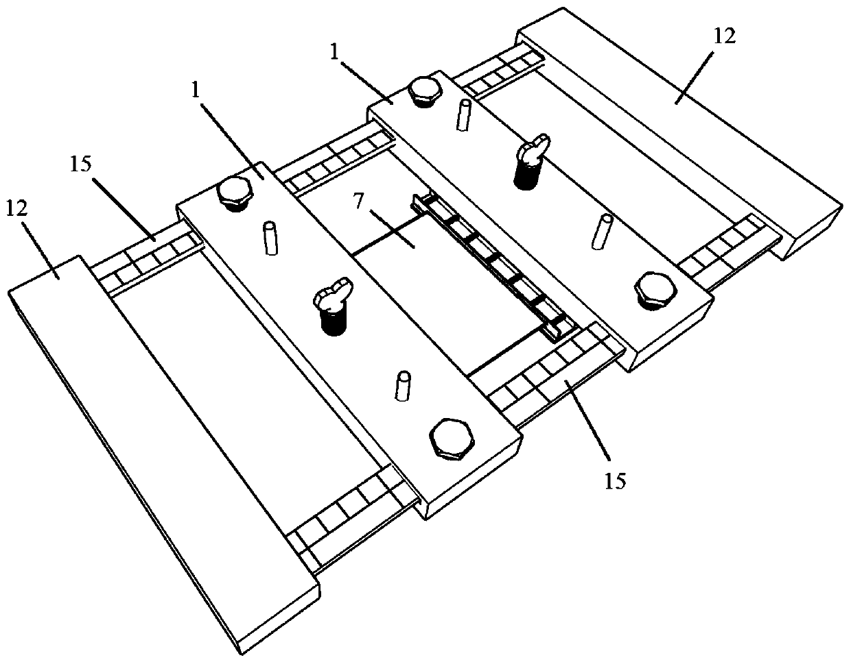
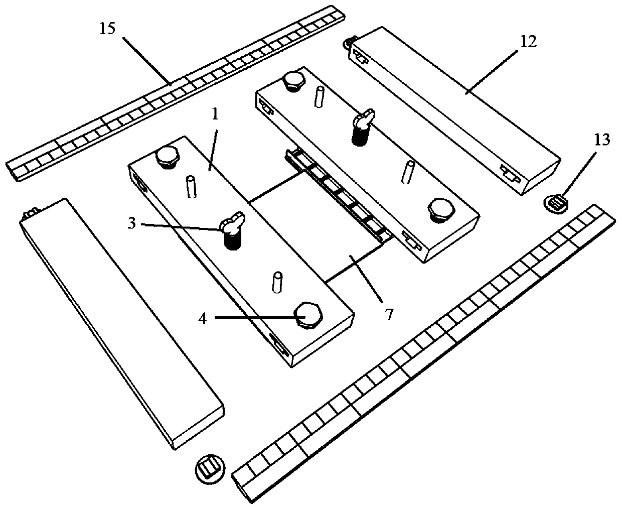
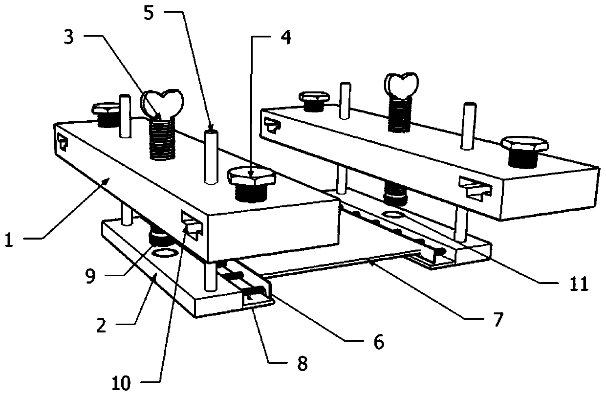
[0026] Such as Figure 1 to Figure 5 As shown, this embodiment discloses a laser confocal microscope biofilm observation stage, including a stage assembly and a biofilm attachment sheet carrying assembly, and the biofilm attachment sheet carrying assembly is used to carry, position and adjust the biofilm attachment Sheet 7, the stage assembly is used to position the carrying assembly of the biofilm attachment sheet on...


PUM


Abstract

The invention discloses a biofilm observation objective table of a laser confocal microscope. The biofilm observation objective table comprises an objective table assembly and a biofilm attachment sheet bearing assembly; the objective table assembly comprises two sliding strips which are arranged in parallel in a spaced mode. The biofilm attachment sheet bearing assembly comprises two moving tables which are arranged in parallel in a spaced mode. The two ends of the moving table are connected with the two sliding strips in a sliding mode respectively, an adjusting block capable of moving up and down is arranged below each moving table, and the bottoms of the opposite side faces of the two adjusting blocks extend outwards by a certain distance to form a supporting table used for containingbiofilm attachment sheets. The biofilm observation objective table is simple in structure, easy to assemble and convenient to operate, can solve the problems of fixing and supporting of the biofilm attachment sheets during observation of the laser confocal microscope in the experiment process, and can also be applied to other electron microscope platforms such as an inverted microscope, a common optical microscope and a fluorescence microscope.

Description

technical field [0001] The invention belongs to the field of laser confocal electron microscope accessories, in particular to a laser confocal electron microscope biofilm observation stage. Background technique [0002] Biofilm (Biofilm) refers to the group of microorganisms attached to the surface of biological or non-biological materials, which are wrapped by extracellular macromolecules secreted by themselves and have certain three-dimensional structural characteristics. Studies have shown that both bacteria and fungi can form biofilms, and biofilms The basic components include: water, macromolecular polymers, adsorbed nutrients, microorganisms themselves and metabolites, etc. At the same time, the formation process of biofilm includes the initial colonization stage, irreversible adhesion stage, structural differentiation stage, development and maturity There are experimental data confirming that each of the above processes will be affected by many factors, such as the ma...

Claims


Application Information

Patent Timeline
Patent Type & Authority Applications(China)
IPC IPC(8): G01B11/24G01B9/04G01N21/84
CPCG01B11/24G01B9/04G01N21/84G01N21/8422
Inventor 周刚王洁乔迪·加西亚·奥哈尔沃莱蒂西亚·加莱拉-拉波特塔施庆珊谢小保彭红王颖思孙廷丽
Owner GUANGDONG INST OF MICROBIOLOGY GUANGDONG DETECTION CENT OF MICROBIOLOGY
Learn More