Supercharge Your Innovation With Domain-Expert AI Agents!

Capacitive touch sensing circuit

A technology of capacitive touch and detection circuit, which is applied in the field of touch detection, can solve the problem of error amount, etc., and achieve the effect of reducing error amount, improving accuracy, and improving signal-to-noise ratio

Active Publication Date: 2020-07-14
RAYDIUM SEMICON
View PDF6 Cites 0 Cited by
  • Summary
  • Abstract
  • Description
  • Claims
  • Application Information

AI Technical Summary

Problems solved by technology

Once the detection capacitor Cb cannot be divisible by the feedback capacitor Cfb, there will be one more count value, and when repeated P times, the count value will have an error of at most P×1

Method used


Image

  • Capacitive touch sensing circuit
  • Capacitive touch sensing circuit
  • Capacitive touch sensing circuit

Examples


Embodiment Construction

[0091] A specific embodiment according to the present invention is a capacitive touch detection circuit. In this embodiment, the capacitive touch detection circuit is a self-capacitive touch detection circuit, but not limited thereto.

[0092] Please refer to Figure 5 , Figure 5 This is a schematic diagram of the capacitive touch detection circuit 5 in this embodiment.

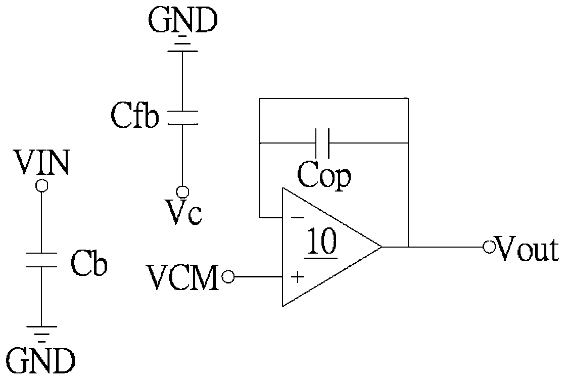
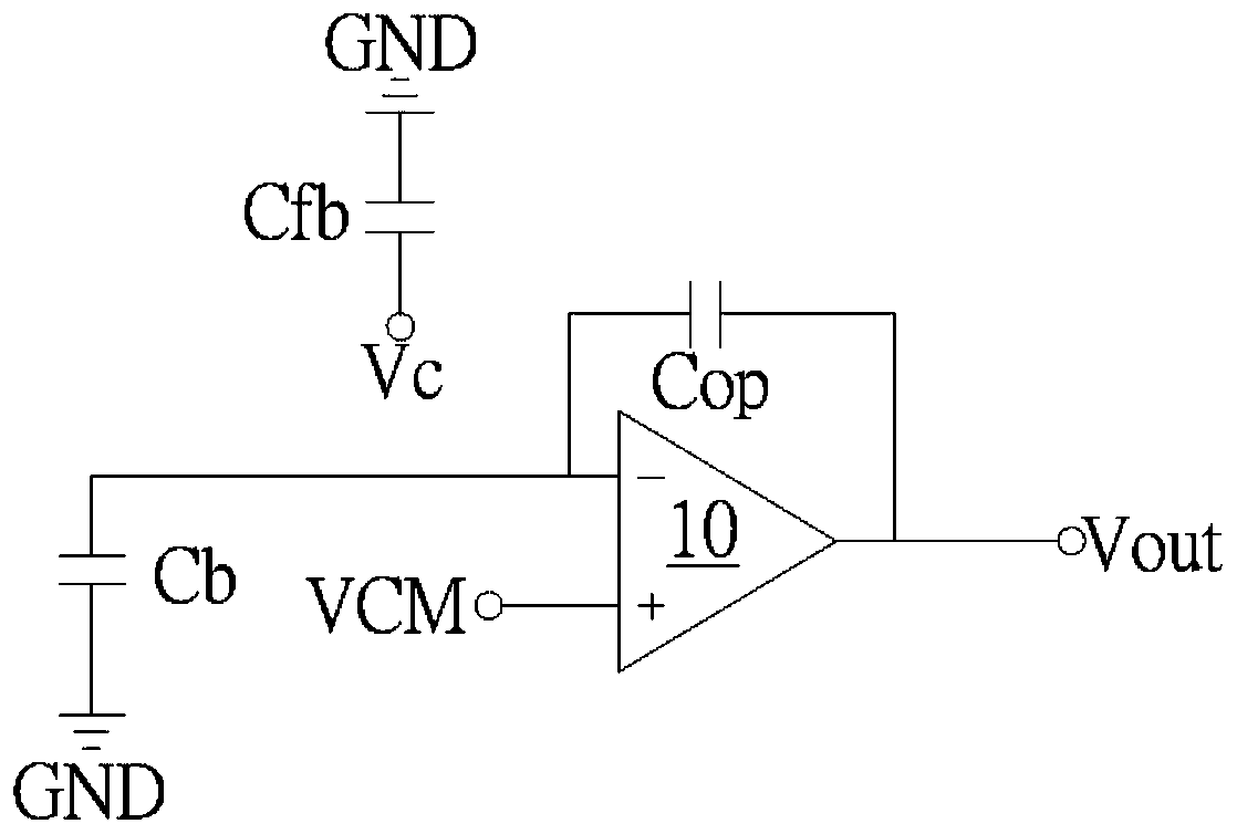
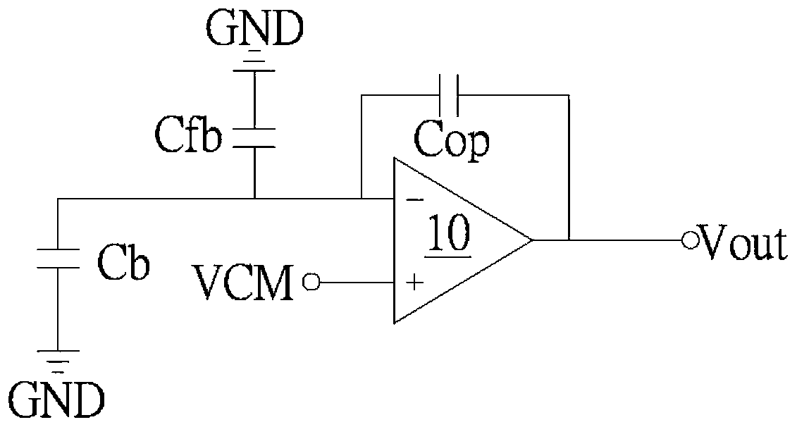
[0093] Such as Figure 5 As shown, the capacitive touch detection circuit 5 may include a first switch S1 to a fourteenth switch S14, an operational amplifier 50, a comparator 52, a detection capacitor Cb, a feedback capacitor Cfb, an amplifier capacitor Cop, and a mutual inductance capacitor Cm.

[0094] The first switch S1 and the second switch S2 are connected in series between the high voltage (receiving end) VH (RX) and the low voltage (receiving end) VL (RX); one end of the detection capacitor Cb is coupled to the first switch S1 and the Between the second switch S2 and its other end is coupled to ...


PUM


Abstract

A capacitive touch sensing circuit includes a first switch to a fourteenth switch, an operational amplifier, a comparator, a detection capacitor, a feedback capacitor, an amplifier capacitor and a mutual inductance capacitor. The tenth switch is coupled between a first node and a second node respectively coupled to a negative input terminal and an output terminal of operational amplifier. The amplifier capacitor is coupled between a third node and a fourth node. The eleventh switch is coupled between the first node and the third node. The twelfth switch is coupled between the second node and the fourth node. The thirteenth switch is coupled between the third node and the second node. The fourteenth switch is coupled between the fourth node and the first node. The capacitive touch sensing circuit sequentially operates under a first charging phase, a first transfer phase, a second charging phase and a second transfer phase.

Description

technical field [0001] The invention relates to touch detection, in particular to a capacitive touch detection circuit. Background technique [0002] In the self-capacitive touch detection circuit, such as figure 1 As shown, in the charging phase (Charge phase), since the detection capacitor Cb is coupled between the input voltage VIN and the ground terminal GND, and the feedback capacitor Cfb is coupled between the compensation voltage Vc and the ground terminal GND, the input The voltage VIN charges the detection capacitor Cb and the compensation voltage Vc charges the feedback capacitor Cfb, the negative input terminal of the operational amplifier 10 - the received voltage is 0 and the positive input terminal of the operational amplifier 10 + is coupled to the common-mode voltage VCM, the operational amplifier The output voltage Vout of the 10 output is equal to the common mode voltage VCM. [0003] Such as figure 2 As shown, in the conduction phase (Transfer phase), ...

Claims


Application Information

Patent Timeline
IPC IPC(8): G06F3/041G06F3/044
CPCG06F3/0416G06F3/044H03K17/962H03K2217/960725H03K17/9622G06F3/0418
Inventor 张智凯陈治雄许有津
Owner RAYDIUM SEMICON
Features
  • R&D
  • Intellectual Property
  • Life Sciences
  • Materials
  • Tech Scout
  • Unparalleled Data Quality
  • Higher Quality Content
  • 60% Fewer Hallucinations
Learn More