
Gear differential type under-actuated three-joint mechanical finger structure and operation method thereof

A mechanical finger and three-joint technology, applied in the direction of manipulators, chucks, manufacturing tools, etc., can solve the problems of difficult control, low reliability, complex structure, etc., and achieve the effect of precise transmission

Active Publication Date: 2020-07-17
XI'AN UNIVERSITY OF ARCHITECTURE AND TECHNOLOGY
View PDF20 Cites 4 Cited by
  • Summary
  • Abstract
  • Description
  • Claims
  • Application Information

AI Technical Summary

Problems solved by technology

The manipulator or the end effector is an important component of the robot. Initially, a single-degree-of-freedom gripper was used to complete some simple operations, such as welding, painting, assembly, etc. Although this type of gripper has a simple structure, convenient control, and strong load capacity, High reliability, but this type of gripper has a single function and lacks flexibility, and can only work for specific tasks. Once the task changes, the end effector needs to be replaced
In this case, out of anthropomorphic imagination, multi-joint multi-fingered dexterous hands have become the development trend of robot end effectors. This multi-joint multi-fingered hand has the advantage of strong shape adaptability and can adapt to many different tasks. However, due to the use of a large number of series joints, the structure is complex, the control is difficult, the load capacity is poor, and the reliability is low.

Method used


Image

  • Gear differential type under-actuated three-joint mechanical finger structure and operation method thereof
  • Gear differential type under-actuated three-joint mechanical finger structure and operation method thereof
  • Gear differential type under-actuated three-joint mechanical finger structure and operation method thereof

Examples


Embodiment Construction

[0038] In describing the present invention, it should be understood that the terms "center", "longitudinal", "transverse", "upper", "lower", "front", "rear", "left", "right", " The orientation or positional relationship indicated by "vertical", "horizontal", "top", "bottom", "inner", "outer", "side", "end", "side" etc. is based on the Orientation or positional relationship is only for the convenience of describing the present invention and simplifying the description, and does not indicate or imply that the referred device or element must have a specific orientation, be constructed and operated in a specific orientation, and thus should not be construed as a limitation of the present invention. In addition, the terms "first" and "second" are used for descriptive purposes only, and cannot be interpreted as indicating or implying relative importance or implicitly specifying the quantity of indicated technical features. Thus, a feature defined as "first" and "second" may explicit...


PUM


Abstract

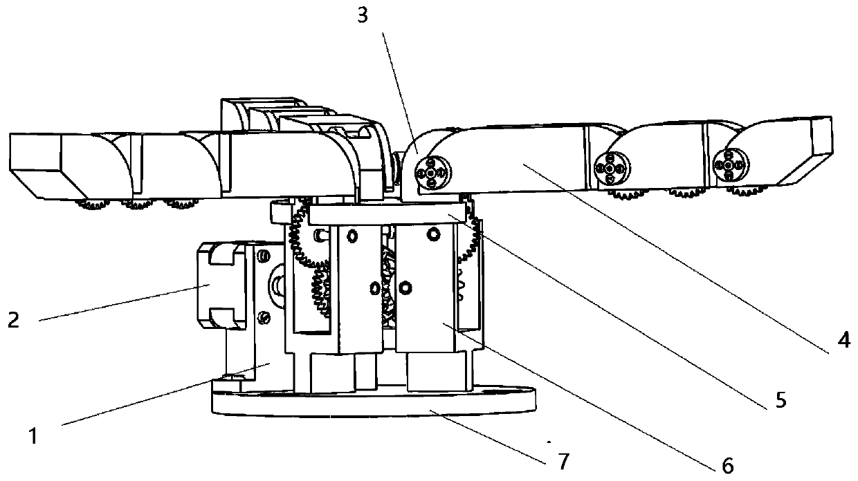
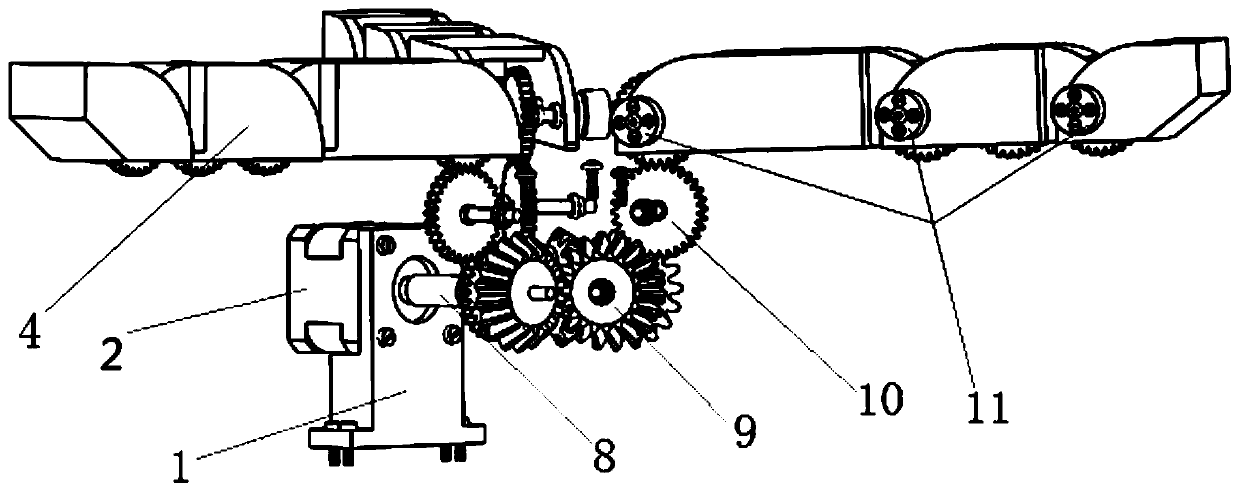
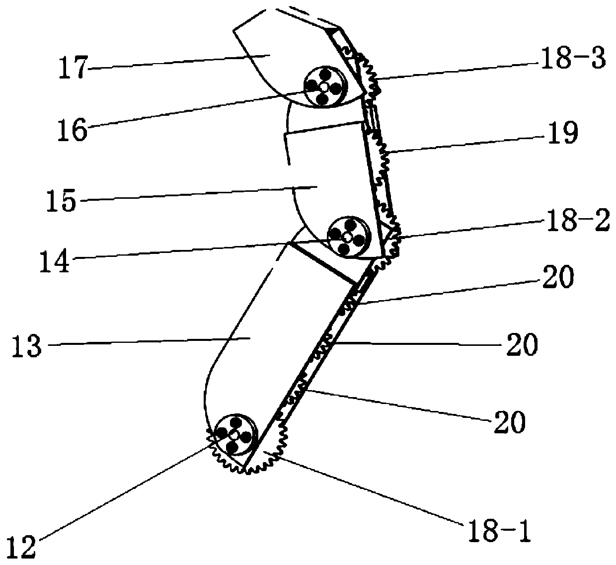
The invention discloses a gear differential type under-actuated three-joint mechanical finger structure and an operation method thereof. The structure comprises three three-joint fingers, wherein thethree three-joint fingers are arranged at an angle of 120 degrees, each three-joint finger comprises a lower knuckle, a middle knuckle and an upper knuckle, the lower knuckles, the middle knuckles andthe upper knuckles are connected in a meshing mode through gears, joint shafts at the joints of the lower knuckles, the middle knuckles and the upper knuckles are provided with decoupling devices forachieving under-actuation correspondingly, the lower knuckles of the three three-joint fingers are connected with a bevel gear transmission system through gears correspondingly, the bevel gear transmission system is formed by meshing four bevel gears with the sub-taper angle being 30 degrees, the bevel gear transmission system is connected with a stepping motor, and the stepping motor drives thebevel gear transmission system to achieve motion control over the three three-joint fingers. The structure is simple in structure, few in driving elements and capable of being self-adaptive to the surface shape of a grabbed object, and then nondestructive and reliable grabbing is achieved.

Description

technical field [0001] The invention belongs to the technical field of mechanical production, and in particular relates to a gear differential underactuated three-joint mechanical finger structure and an operation method thereof. Background technique [0002] With social development and scientific and technological progress, robots are widely used in manufacturing, and in space exploration that emphasizes minimal maintenance requirements, the use of robots is more attractive. The manipulator or the end effector is an important component of the robot. Initially, a single-degree-of-freedom gripper was used to complete some simple operations, such as welding, painting, assembly, etc. Although this type of gripper has a simple structure, convenient control, and strong load capacity, Reliability is high, but this type of gripper has a single function and lacks flexibility, and can only work for a specific task. Once the task changes, the end effector needs to be replaced. In thi...

Claims


Application Information

Patent Timeline
Patent Type & Authority Applications(China)
IPC IPC(8): B25J15/00B25J15/02
CPCB25J15/0009B25J15/0213
Inventor 郭瑞峰胡星闫浩贾榕黄亚东
Owner XI'AN UNIVERSITY OF ARCHITECTURE AND TECHNOLOGY
Learn More