Horizontally-arranged hydraulic cylinder dynamic adjusting suspension

A dynamically adjusted, hydraulic cylinder technology used in suspension, interconnection systems, transportation and packaging to reduce vertical loads and torque differences

Active Publication Date: 2020-07-17
HEFEI UNIV OF TECH
View PDF14 Cites 4 Cited by
  • Summary
  • Abstract
  • Description
  • Claims
  • Application Information

AI Technical Summary

Problems solved by technology

Therefore, the prior art does not have a vehicle suspension system that can adapt to the road surface to adjust the stabilizer bar without energy input, especially a suspension system that can dynamically adjust roll and off-road performance.

Method used


Image

  • Horizontally-arranged hydraulic cylinder dynamic adjusting suspension
  • Horizontally-arranged hydraulic cylinder dynamic adjusting suspension
  • Horizontally-arranged hydraulic cylinder dynamic adjusting suspension

Examples


Embodiment 1

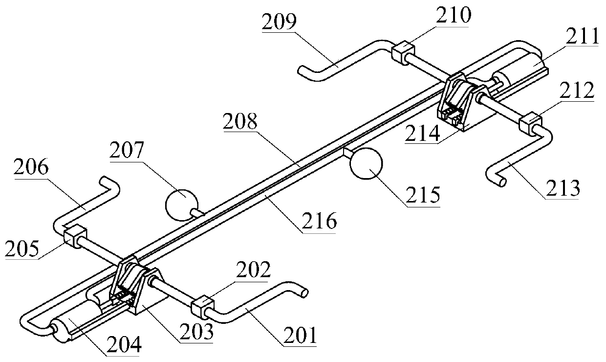
[0037] Such as figure 1 As shown, the horizontally arranged hydraulic cylinder dynamic adjustment suspension of the present invention includes at least two energy conversion units and at least one hydraulic adjustment unit. The energy adjustment unit is arranged between the two energy conversion units through pipelines. The number of energy adjustment units can be one, or two or even more. The energy conversion unit at least includes a hydraulic cylinder and a torque transmission mechanism connected to each other, and is used to convert the energy generated by the torque deformation of the connecting rod connected with the wheel into hydraulic energy. Preferably, the energy conversion units are not limited to two, but may also be three, four, five, six or even more.

[0038] At least one energy conversion unit is respectively connected to the front wheels of the vehicle through at least two connecting rods, and at least one energy conversion unit is respectively connected to...

Embodiment 2

[0056] The horizontally arranged hydraulic cylinder dynamic adjustment suspension of the present invention at least includes at least two energy conversion units and at least one hydraulic adjustment unit. The number of energy conversion units is not limited to 2, and may be more. The energy adjustment unit is arranged between the two energy conversion units through pipelines.

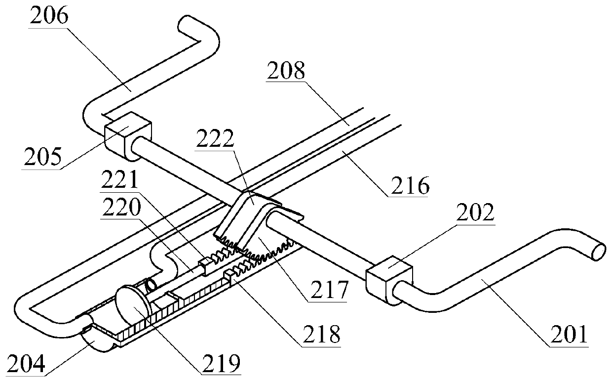
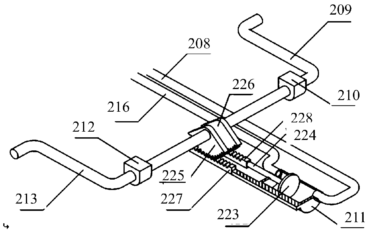
[0057] Such as Image 6 with Figure 7 As shown, the energy conversion unit at least includes a horizontally arranged hydraulic cylinder and a torque transmission mechanism arranged in the hydraulic cylinder, and the torque transmission mechanism includes at least two rotary pistons that can rotate relative to each other. The two rotary pistons in one hydraulic cylinder are respectively connected to the front wheels of the vehicle through at least one connecting rod, and the two rotary pistons in the other hydraulic cylinder are respectively connected to the rear wheels of the vehicle through at leas...

Embodiment 3

[0070] This embodiment provides test results and comparative analysis of the horizontally arranged hydraulic cylinder dynamic adjustment suspension of the present invention and the suspension of the prior art.

[0071] The automobile suspension system of the present invention is dynamically adjusted. The dynamic response of the vehicle is studied through the simulation experiments of different working conditions, and the vehicle equipped with the present invention is compared with the vehicle equipped with the conventional transverse connecting rod, as shown in Table 1 to Table 2.

[0072] Table 1 Main parameters of the vehicle

[0073]

[0074] 1) Snake experiment

[0075] In order to verify the influence of the suspension system on the anti-roll performance of the vehicle, follow the Figure 10 The serpentine path shown is tested. Figure 10 Shows the change in steering wheel angle. Figure 10 In , the ordinate represents the steering wheel angle, and the abscissa rep...


PUM


Abstract

The invention relates to a horizontally-arranged hydraulic cylinder dynamic adjusting suspension. The suspension at least comprises two energy conversion units and a hydraulic adjusting unit, whereinan energy adjusting unit is arranged between the two energy conversion units through a pipeline; each energy conversion unit at least comprises a hydraulic cylinder and a torque transmission mechanismwhich are connected with each other; one of the energy conversion units is respectively connected with front wheels of the vehicle through two connecting rods; the other energy conversion unit is respectively connected with rear wheels of the vehicle through two connecting rods; under the condition that the wheels are stressed, a torque transmission mechanisms associate the torsion state of the connecting rods with the hydraulic state of the hydraulic cylinders so as to change the piston movement state of the hydraulic cylinders on the basis of the torque of the connecting rods. Therefore, under the condition that the hydraulic pressure difference occurs between the hydraulic cylinders with the connection relation, the hydraulic pressure adjusting unit adjusts the hydraulic pressure states of the hydraulic cylinders in a hydraulic pressure absorbing and/or releasing mode, the torsion state of the connecting rods is correspondingly adjusted based on the hydraulic pressure states of thehydraulic cylinders, and therefore the vertical load of wheels on a vehicle body is reduced.

Description

technical field [0001] The invention relates to the technical field of automobiles, in particular to a horizontally arranged hydraulic cylinder dynamic adjustment suspension. Background technique [0002] Vehicles with rigid axles typically have sway bars that limit lateral movement of the wheels relative to the vehicle's body. The sway bar or track bar typically comprises a rigid bar extending laterally in the same plane as the axle to connect one end of the axle to the body of the vehicle on the opposite side. The bar is attached on either end with a pivot that only allows the bar to rotate up and down so that the axle can only move vertically. Therefore, the stabilizer bar is generally mounted to the frame of the vehicle body through a bracket. The bracket must withstand lateral forces. A suspension system, such as an air suspension, can be mounted in the same area of ​​the body to accommodate the vertical movement of the axle and wheels relative to the body. [0003]...

Claims


Application Information

Patent Timeline
Patent Type & Authority Applications(China)
IPC IPC(8): B60G21/06
CPCB60G21/06B60G2204/8304B60G2204/8306
Inventor 郑敏毅钟伟民张农陈桐朱波罗亮
Owner HEFEI UNIV OF TECH
Why Eureka
Try Eureka