Adjustable sound-proof heating composite floor

A technology of composite flooring and shape adjustment, which is applied in the field of flooring to solve the height difference and improve the effect of sound insulation

Active Publication Date: 2020-07-17
东营华德利新材料有限公司
View PDF8 Cites 3 Cited by
  • Summary
  • Abstract
  • Description
  • Claims
  • Application Information

AI Technical Summary

Problems solved by technology

[0006] The purpose of the present invention is to overcome the above-mentioned defects existing in the existing floor, and propose an adjustable sound-insulating heating composite floor, which can effectively suppress the thermal deformation of the floor by setting the reinforced keel, and solve the thermal stability problem of the floor

Method used


Image

  • Adjustable sound-proof heating composite floor
  • Adjustable sound-proof heating composite floor
  • Adjustable sound-proof heating composite floor

Examples


Embodiment 1

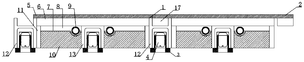
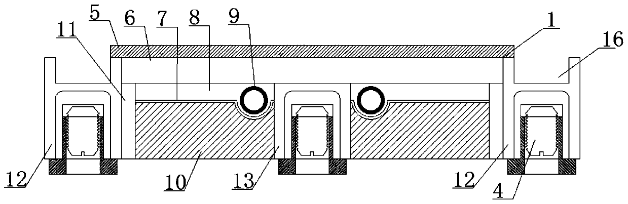
[0073] (1) The 0.8mm thick PVC decorative veneer and the 5mm thick solid wood composite layer are laminated by dry hot pressing. The solid wood composite layer is one layer of eucalyptus and one layer of pine. The layers are laminated by adhesive under high temperature and pressure;

[0074] (2) The sound insulation layer is made of glass fibers of different diameters and is dehydrated and pressed by wet beating method. The composition of each fiber component is as follows:

[0075] Flame blown glass wool:

[0076] Average diameter 1.5-2.5μm 25 parts by mass

[0077] Average diameter 2.5-3.5μm 30 parts by mass

[0078] 20 parts by mass with an average diameter of 3.5-4.0 μm;

[0079] Centrifugal blown glass wool:

[0080] Average diameter 4.5-5.5μm 15 parts by mass

[0081] 10 parts by mass of an average diameter of 5.5 to 6.0 μm.

[0082] The thickness is 1.5cm to 5.5cm, and the sound insulation layer is made of the above-mentioned centrifugal fiber cotton and flame fib...

Embodiment 2

[0099] Adopt the composite floor structure identical with embodiment 1. The parameters different from Example 1 are as follows:

[0100] The composition of each fiber component of the sound insulation layer is as follows:

[0101] Flame blown glass wool:

[0102] Average diameter 1.5-2.5μm 20 parts by mass

[0103] Average diameter 2.5-3.5μm 25 parts by mass

[0104] Average diameter 3.5-4.0μm 18 parts by mass

[0105]Centrifugal blown glass wool:

[0106] Average diameter 4.5-5.5μm 25 parts by mass

[0107] Average diameter 5.5~6.0μm 12 parts by mass

[0108] The parameters of the sound insulation layer are shown in Table 3.

[0109] Table 3. The parameters of the sound insulation layer of the composite floor of embodiment 2

[0110]

[0111] The lower surface of the fiber sound insulation board is pasted with crystalline nylon mesh cloth with a thickness of 1.2mm, and the upper surface is covered with a layer of aluminum foil slow-release film with a thickness of ...


PUM


Abstract

The invention belongs to the field of floors and particularly relates to an adjustable sound-proof heating composite floor. The composite floor comprises a negative plate and a positive plate which are matched with each other, wherein each of the negative plate and the positive plate comprises a heat conducting layer and a decoration layer bonded on the upper surface of the heat conducting layer,side keels are arranged on two sides of the negative plate in the longitudinal direction, upper parts of the inner sides of the side keels are fixedly connected with the side walls of the heat conducting layers, and a clamp slot is formed in the top of each side keel; clamp strips are arranged on two sides of the positive plate in the longitudinal direction, each clamp strip is fixedly connected to the lower surface of the decoration layer, and the two clamp slots of the negative plate can be spliced with the clamp strips of the adjacent positive plate respectively; a central keel is arrangedin the center below the heat conducting layers of the negative plate and the positive plate in the longitudinal direction; and a heating pipe is arranged between the central keel and each side keel. According to the floor, the reinforcing keels are arranged, so that thermal deformation of the floor under heating can be effectively suppressed, and the problem of thermal stability of the floor is solved.

Description

technical field [0001] The invention belongs to the field of floors, and relates to a composite floor used for interior decoration in the field of civil buildings, in particular to an adjustable sound-insulating and heating composite floor. Background technique [0002] So far, poor sound insulation of floors is an important problem that the housing industry has not been able to effectively solve. Limited by the existing construction technology, the reinforced concrete structure cannot well block the transmission of the sound from the upper and lower floors between the floors, which makes it easy for the occupants to hear the noise of the neighbors upstairs and downstairs. The sound of children running and jumping upstairs, the sliding sound of moving furniture, the vibration of washing machine, etc. Conventional reinforced concrete with a thickness of about 100mm is good for air-borne sound insulation, but has little effect on vibration and impact sound. The sound insulat...

Claims


Application Information

Patent Timeline
Patent Type & Authority Applications(China)
IPC IPC(8): E04F15/02E04F15/18E04F15/20F24D3/16
CPCE04F15/02E04F15/02038E04F15/181E04F15/206E04F2201/026E04F2201/042E04F2290/023E04F2290/041E04F2290/043F24D3/16
Inventor 周玉成王玉涛王艳龙刘震刘红艳牛海明
Owner 东营华德利新材料有限公司
Why Eureka
Try Eureka