Spinning type tracking reflecting light condensing device

A concentrating device and spin-type technology, which is applied in the direction of solar ray concentration, solar collector controller, lighting and heating equipment, etc., can solve the problem of light energy waste and achieve the effect of improving photoelectric conversion efficiency

Inactive Publication Date: 2020-07-17
宜昌朗途科技开发有限公司
View PDF0 Cites 0 Cited by
  • Summary
  • Abstract
  • Description
  • Claims
  • Application Information

AI Technical Summary

Problems solved by technology

[0003] In order to overcome the defect that the existing solar concentrating power generation system cannot always keep the concentrating point coincident with the location of the heat absorber, resulting in a waste of light energy, the present invention provides a spin-type tracking reflective concentrating device, no matter in a day How does the direction of sunlight change? The height of sunlight rises and falls with the change of seasons throughout the year. The concentrated light formed by reflecting sunlight from multiple reflectors is always irradiated on the heat absorber at the top of the receiving tower to achieve high efficiency. use light energy to generate electricity

Method used


Image

  • Spinning type tracking reflecting light condensing device
  • Spinning type tracking reflecting light condensing device
  • Spinning type tracking reflecting light condensing device

Examples


Embodiment 1

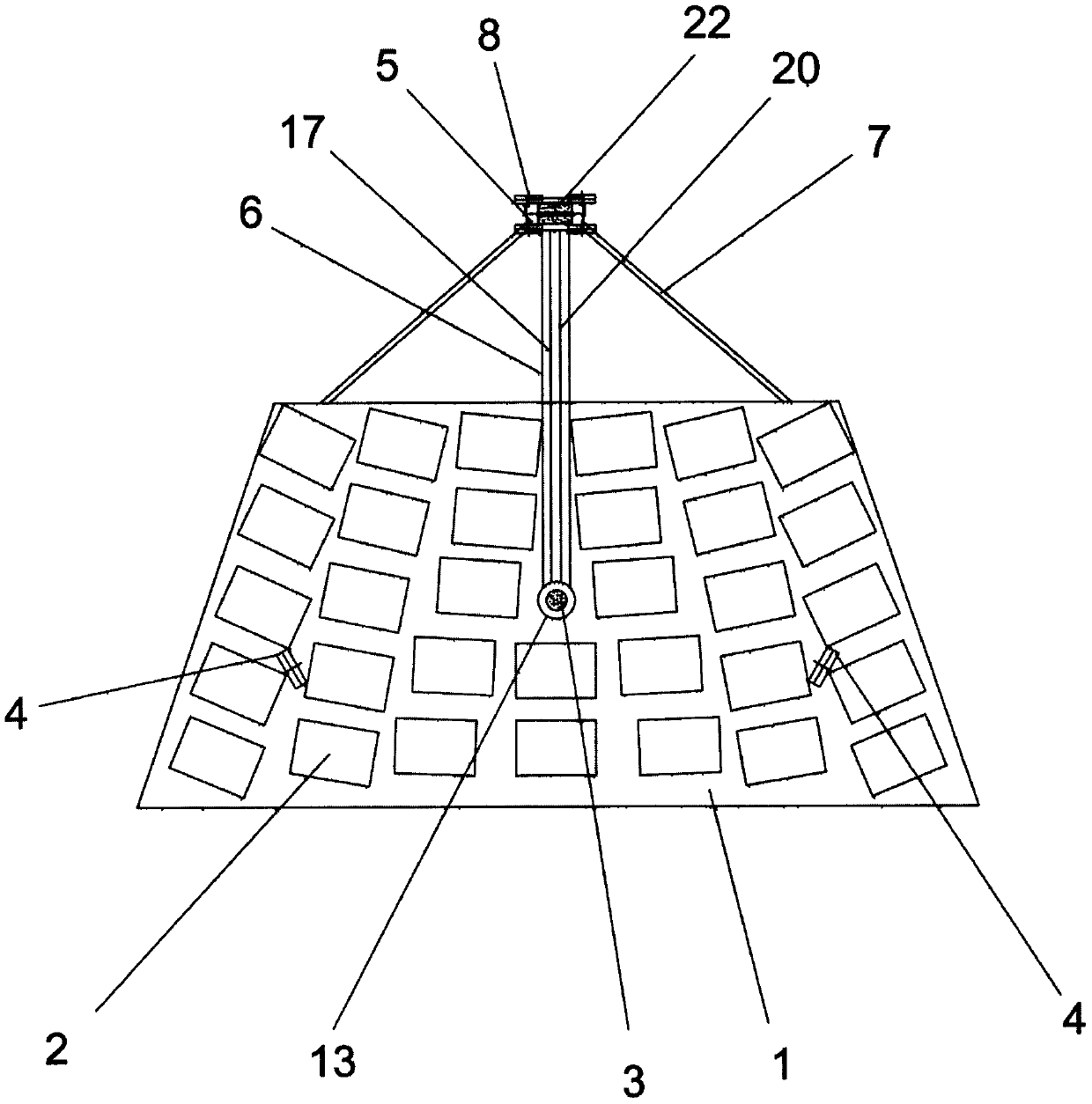
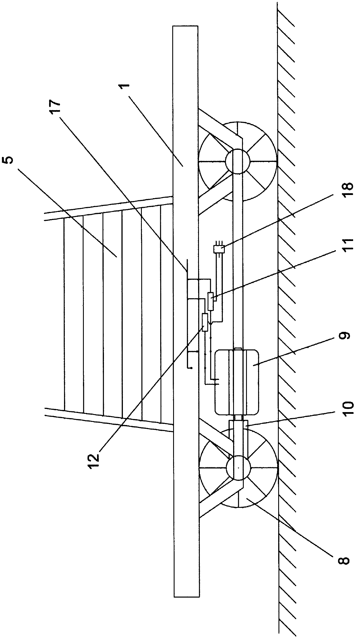
[0021] The spin-type tracking reflective concentrating device includes a horizontal frame 1, on which a plurality of reflectors are installed to form a reflector array 2, and the bottom of the horizontal frame 1 has a rotating shaft 3, which is perpendicular to the ground and extends into the ground below. Two load-bearing wheels 4 are installed at the bottom of the horizontal frame 1, and the load-bearing wheels 4 are in contact with the ground. Another concentrating tower 5 is rigidly connected with the horizontal frame 1 through the connecting arm 6, and a triangular support arm 7 is respectively arranged on both sides of the connecting arm 6, and the triangular support arm 7 is connected with the horizontal frame 1 and the concentrating tower 5 to play the role of Fixed the effect of Focus Tower 5. Such as figure 2 , four load-bearing driving wheels 8 are installed below the focusing tower 5, and each bearing driving wheel 8 bears the weight of the focusing tower 5 and ...

Embodiment 2

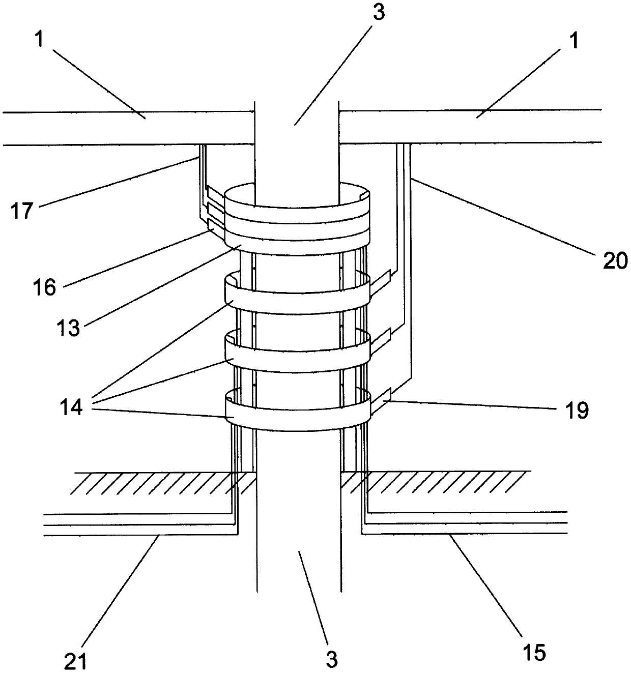
[0034] Such as Figure 8 , the rotating shaft 3 can be arranged at the bottom of the horizontal frame 1 or at the bottom of the connecting arm 6 . Compared with being arranged at the bottom of the horizontal frame 1, the rotation axis 3 is arranged at the bottom of the connecting arm 6, which can reduce the rotation radius of the focusing tower 5 and the horizontal frame 1 around the rotation axis 3, and occupy a smaller site area.

Embodiment 3

[0036] The concentrating tower 5 can directly contact the ground through the load-bearing driving wheel 8, and also can lay a circular track on the ground, and the load-bearing driving wheel 8 is placed on the circular track. The ring track takes the rotating shaft 3 as the center and the distance from the rotating shaft 3 to the load-bearing driving wheel 8 as the radius, so that the focusing tower 5 rotates on the track around the rotating shaft 3 . Compared with the load-bearing drive wheel 8 in direct contact with the ground, the annular track can provide the load-bearing drive wheel 8 with less rolling friction resistance.


PUM


Abstract

The invention discloses a spinning type tracking reflecting light condensing device. The spinning type tracking reflecting light condensing device comprises a horizontal frame and a reflecting mirrorarray, a light condensing tower is additionally mounted, a dual-way driving motor and a speed reducer are arranged on the lower portion of the light condensing tower, a light condensing point positionsensor is mounted on the top end of the light condensing tower, a reflecting mirror vertical angle adjusting mechanism is mounted on the horizontal frame, a controller is connected with above devices, when the irradiating direction of the sun is changed and the light condensing point deviates from a heat absorber, the light condensing point position sensor induces the changes, the controller instructs the dual-way driving motor to operate, the light condensing tower rotates around a rotating shaft, the horizontal frame is driven to rotate to adjust the orientation, or the reflecting mirror vertical angle adjusting mechanism is instructed to adjust the vertical angles of all light reflecting mirrors, the light condensing point is moved to the heat absorber again, through real-time adjusting of the light condensing point in the horizontal and vertical directions, the light condensing point is on the heat absorber on the top end of the light condensing tower all the time, and the photoelectric converting efficiency is improved.

Description

technical field [0001] The invention relates to a light energy collection device, in particular to a spin-type tracking reflection light concentrating device. Background technique [0002] In the existing concentrated solar power generation system, several large reflectors are installed on the ground to form an array to reflect and gather sunlight to the heat absorber on the receiving tower. The heat absorber converts solar energy into heat energy to drive the generator to run. In the prior art, when the sun faces the reflector array, the light reflected by all the reflectors is gathered on the heat absorber to form a concentrating point. However, because the installation positions of the reflector and the heat absorber are fixed, and the angle of the sun’s irradiation will continue to change within a day, it will cause the spot where the reflector array reflects the sunlight and the heat absorber on the receiving tower to be in the same position. The positions cannot alway...

Claims


Application Information

Patent Timeline
IPC IPC(8): F24S23/70F24S50/20F24S80/00
CPCY02E10/47
Inventor 王智勇
Owner 宜昌朗途科技开发有限公司
Why Eureka
Try Eureka