
Quick turning method for photoelectric equipment by combining bang-bang control and overshoot-free predictive control

A technology of predictive control and optoelectronic equipment, applied in the control of using feedback, exploration of optical devices, etc., can solve problems such as system instability, and achieve the effects of strong anti-interference ability, improved rapidity, and simple control structure

Active Publication Date: 2020-07-17
INST OF OPTICS & ELECTRONICS - CHINESE ACAD OF SCI
View PDF9 Cites 1 Cited by
  • Summary
  • Abstract
  • Description
  • Claims
  • Application Information

AI Technical Summary

Problems solved by technology

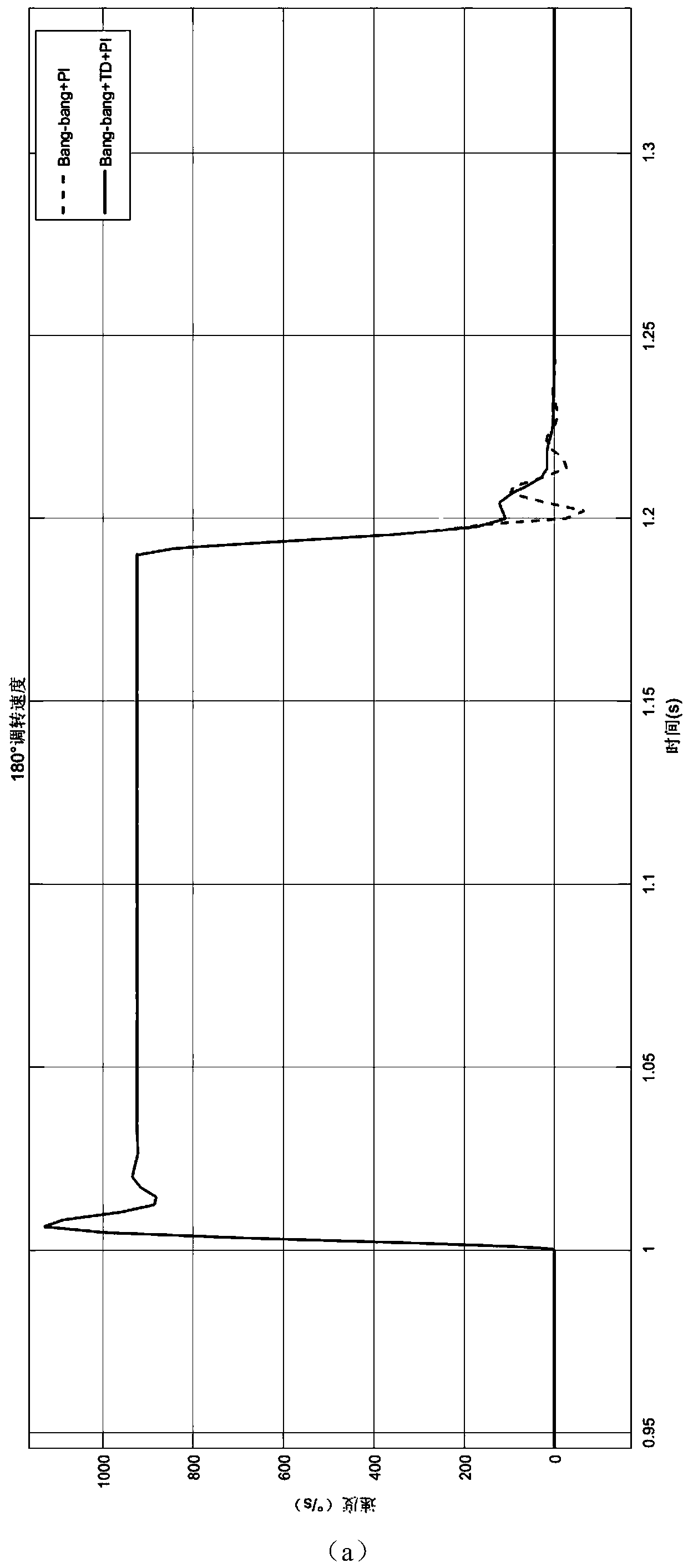
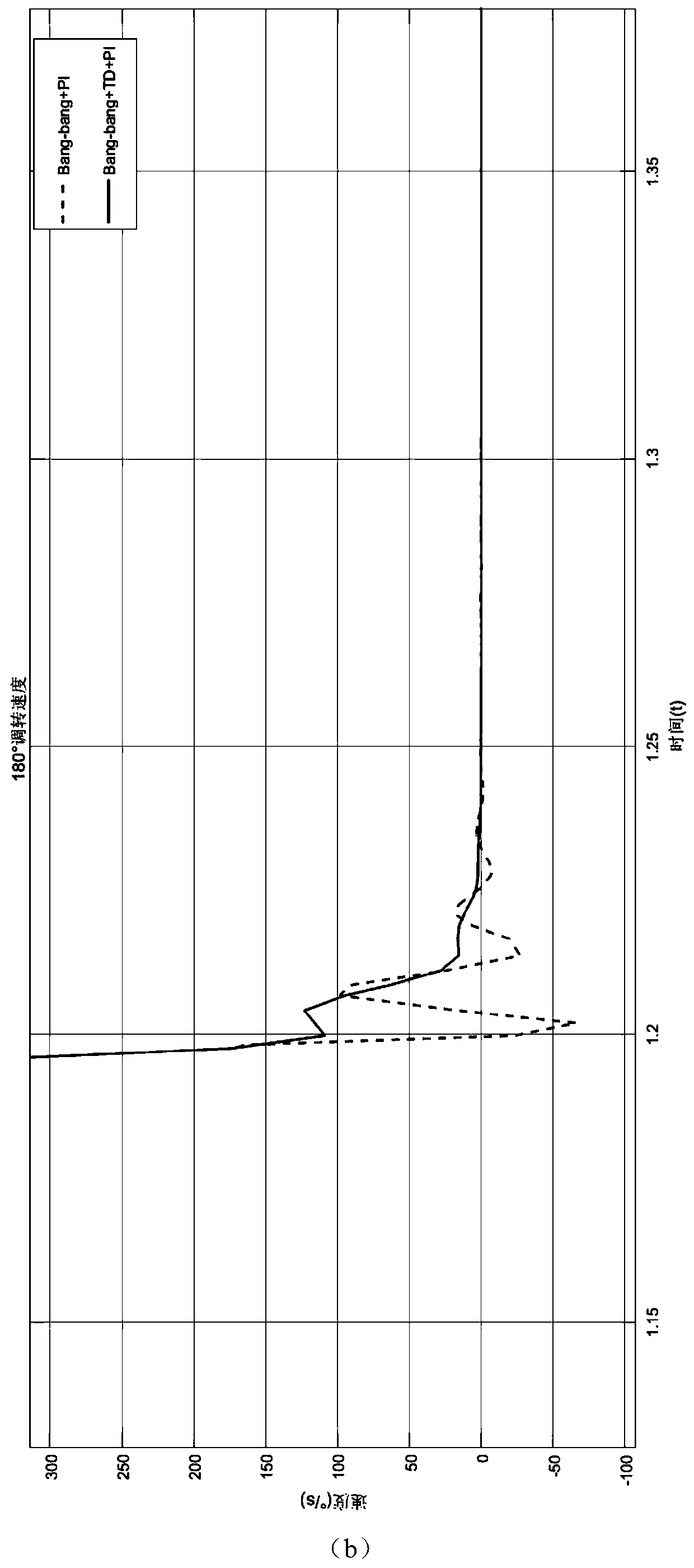
[0003] Aiming at the problem that the bang-bang control based on the photoelectric equipment transfer process will cause system instability when the error is small, this paper proposes a method that combines bang-bang control and no-overshoot predictive control. When the system receives the guidance signal, the bang -bang controls the driving motor to rotate with the maximum driving force, and switches to non-overshoot predictive control when approaching the target, quickly approaching the guide position and meeting the target capture conditions, using bang-bang control to turn the speed fast and non-overshoot predictive control can make the system fast The characteristics of switching to the tracking stage to realize the stable and fast target acquisition control of the photoelectric tracking platform

Method used


Image

  • Quick turning method for photoelectric equipment by combining bang-bang control and overshoot-free predictive control
  • Quick turning method for photoelectric equipment by combining bang-bang control and overshoot-free predictive control
  • Quick turning method for photoelectric equipment by combining bang-bang control and overshoot-free predictive control

Examples


Embodiment Construction

[0023] The specific implementation manners of the present invention will be described in detail below in conjunction with the accompanying drawings.

[0024] Such as figure 1 Shown is a block diagram of a method for fast switching of photoelectric equipment combining bang-bang control and non-overshoot predictive control according to the present invention. Wherein comprise encoder position loop, gyro speed loop, bang-bang controller, no overshoot controller; Adopt described device to realize the specific implementation steps of fast transfer control method as follows:

[0025] Step (1): Obtain the velocity object model G of the platform through the frequency response tester v (s). The torque motor used in the present invention has good linearity, wide speed regulation range, strong quick response ability, strong stability and high tracking accuracy at low speed, and the parameter model of the system can be obtained according to the physical mechanism modeling, and then throu...


PUM


Abstract

The invention discloses a quick turning method for photoelectric equipment by combining bang-bang control and overshoot-free predictive control. According to the method, the advantage that bang-bang control is high in large-range turning speed is combined, and no-overshoot prediction control is used in the turning process, so that the turning time of the system is shortened, and the target capturing state and the tracking state can be stably switched. The system receives a guide signal and controls a driving motor to turn with the maximum driving force through bang-bang, and when approaching the target, the system is switched to non-overshoot prediction control to quickly approach the target and meet a target capture condition. According to the method, the system is optimized from the minimum time control problem; the advantage that the bang-bang control is high in turning speed in a large range is brought into full play; the characteristics that the system can quickly enter a steady state within limited time without overshoot prediction control energy are utilized, so that oscillation is not generated when the position of the system enters an error band; the advantages of the twocontrol methods are complementary; and the whole-process turning speed and stability of the photoelectric equipment are improved under the condition that the cost is not increased.

Description

technical field [0001] The invention belongs to the field of fast switching of photoelectric tracking systems, and specifically relates to a fast switching method of photoelectric equipment combined with bang-bang control and non-overshoot predictive control, which is mainly used to shorten the system switching time, thereby further ensuring target image capture conditions and enhancing The performance of the photoelectric tracking system in the fast turnaround is improved. Background technique [0002] In order to adapt to modern optoelectronic equipment tracking the target, it is required that the equipment should be transferred to the target position in the shortest possible time in the environment where the target appears random, to meet the image capture conditions and maintain stable tracking, so the equipment transfer capability directly affects the target ability to track. In order to achieve the purpose of fast turnaround, the photoelectric equipment is required no...

Claims


Application Information

Patent Timeline
IPC IPC(8): G05D3/20G01V8/10
CPCG05D3/20G01V8/10
Inventor 唐茂雯夏运霞陈兴龙包启亮
Owner INST OF OPTICS & ELECTRONICS - CHINESE ACAD OF SCI
Learn More