Piezoelectric actuating unit DC/AC inverter current spike suppression method

A current peak and piezoelectric actuation technology, which is applied in the direction of electrical components, output power conversion devices, etc., can solve problems such as large current peaks

Active Publication Date: 2020-07-17
HARBIN INST OF TECH
View PDF2 Cites 0 Cited by
  • Summary
  • Abstract
  • Description
  • Claims
  • Application Information

AI Technical Summary

Problems solved by technology

[0005] The present invention is to solve the problem of large current peak in the traditional inverter topology

Method used


Image

  • Piezoelectric actuating unit DC/AC inverter current spike suppression method
  • Piezoelectric actuating unit DC/AC inverter current spike suppression method
  • Piezoelectric actuating unit DC/AC inverter current spike suppression method

Examples


specific Embodiment approach 1

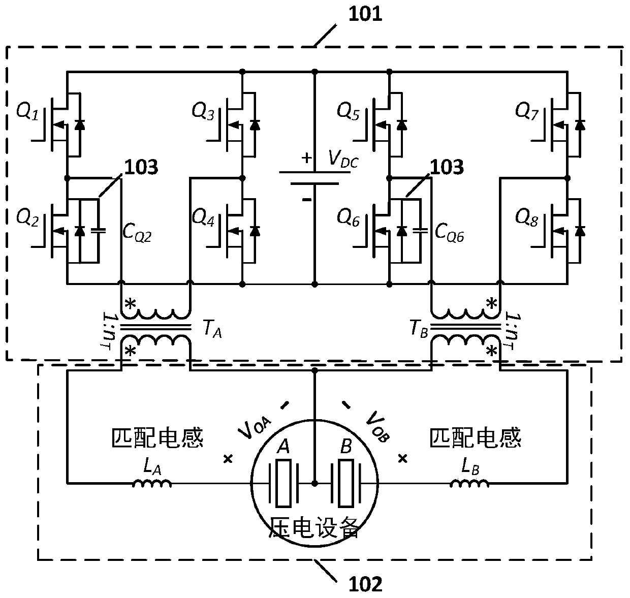
[0050] Specific embodiment one: a piezoelectric actuator unit DC / AC inverter current spike suppression method is characterized in that it consists of a full-bridge inverter circuit (101) comprising a Snubber circuit, a matching circuit (102), and a Snubber capacitor ( 103) The calculation method of the capacitance value and the calculation method of the switch dead time.

specific Embodiment approach 2

[0051] Specific Embodiment 2: This embodiment is a further description of the method for suppressing current spikes in a piezoelectric actuator unit DC / AC inverter described in Specific Embodiment 1. Refer to figure 1 Describe this embodiment in detail, the full-bridge inverter circuit comprising the Snubber circuit described in this embodiment is made up of eight power switch tubes and two Snubber capacitors (102), specifically including No. 1 MOS tube (Q 1 ), No. 2 MOS tube (Q 2 ), No. 3 MOS tube (Q 3 ), MOS tube No. 4 (Q 4 ), No. 5 MOS tube (Q 5 ), No. 6 MOS tube (Q 6 ), MOS tube No. 7 (Q 7 ), No. 8 MOS tube (Q 8 ), Snubber Capacitor #1 (C Q2 ), the second Snubber capacitor (C Q6 ), Transformer No. 1 (T A ) and No. 2 transformer (T B ), there is a freewheeling diode directly between the drain and the source of each MOS transistor,

[0052] No. 1 MOS tube (Q 1 ) drain, the third MOS tube (Q 3 ) drain, the fifth MOS tube (Q 5 ) of the drain and the seventh MOS tu...

specific Embodiment approach 3

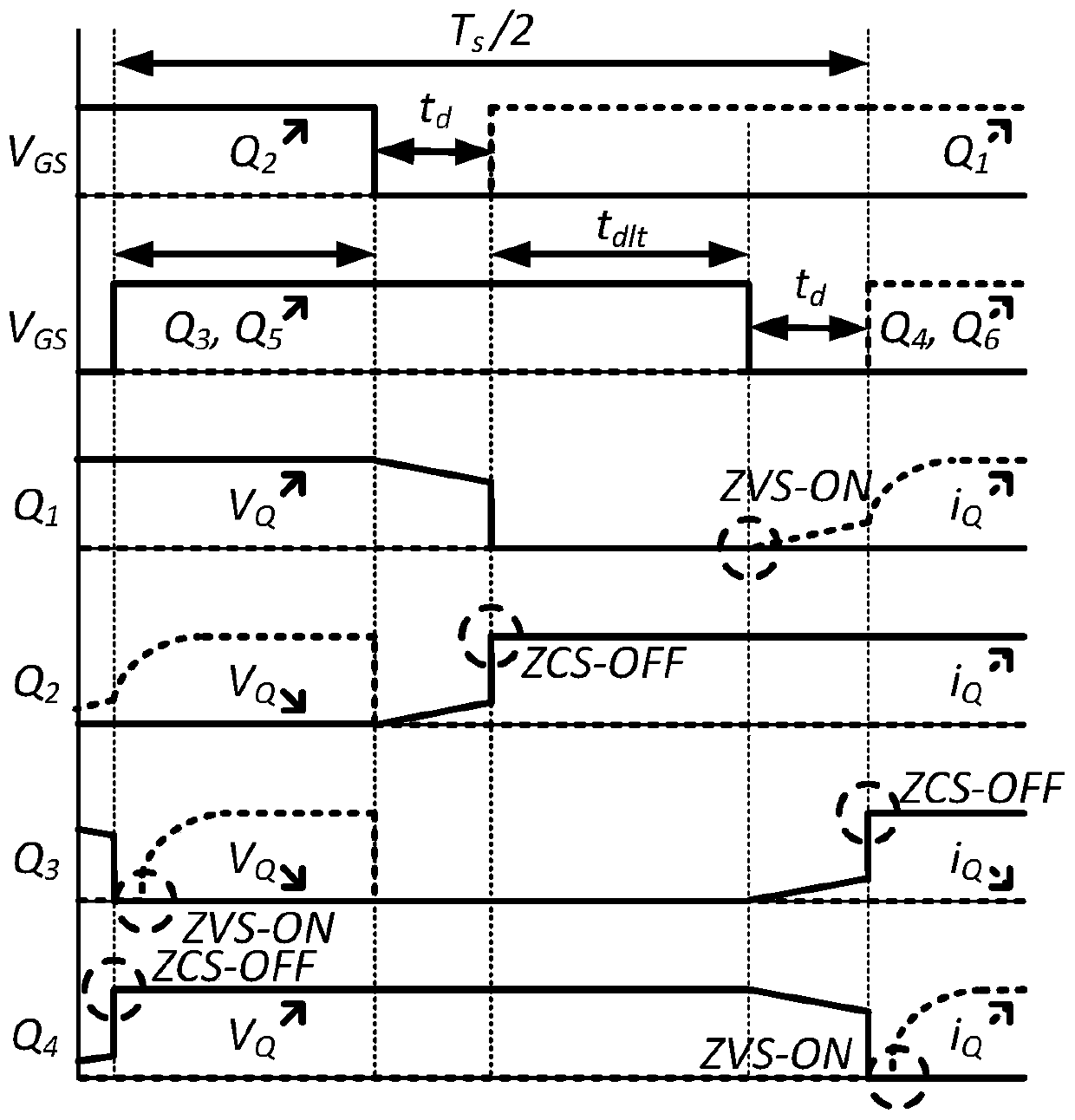
[0064] Specific embodiment three: This embodiment is a further description of the full-bridge inverter circuit including the snubber circuit described in specific embodiment two. In this embodiment, the switching control logic applied to the bases of the eight power switch tubes:

[0065] No. 1 power switch tube (Q 1 ) and No. 2 power switch tube (Q 2 ) There is a specific dead time between the switch states, the third power switch (Q 3 ) and No. 4 power switch tube (Q 4 ) has the same specific dead time between switching states, the fifth power switch (Q 5 ) and No. 6 power switch tube (Q 6 ) has the same specific dead time between the switch states, the seventh power switch (Q 7 ) and No. 8 power switch tube (Q 8 ) has the same specific dead time between the switching states, the first power switch (Q 1 ) and No. 3 power switch tube (Q 3 ) There is a specific delay time between the switch states, the second power switch tube (Q 2 ) and No. 4 power switch tube (Q 4 T...


PUM


Abstract

The invention discloses a DC/AC inverter current peak suppression method, and relates to the technical field of driving of two-phase actuators. The invention solves the problem of large current peak in a traditional driving circuit. According to the method provided by the invention, the resonance between the series inductor and the buffer capacitor is realized by optimally designing and matching the inductance value of the inductor, the capacitance value of the buffer capacitor, the dead time value and the delay time value, so that the zero-voltage and zero-current switching of a power tube can be realized. Two signal input ends of a two-phase full-bridge inverter are connected with a power grid, two signal output ends of the two-phase full-bridge inverter circuit are connected with the two signal input ends of a matching circuit respectively, and the output ends of the matching circuit are used for being connected with a two-phase motor.

Description

technical field [0001] The present invention relates to the drive technology of two-phase actuators, more specifically, relates to the DC / AC inverter current spike suppression method for controlling two-phase motors; the scheme of the present invention is especially suitable for driving various types of two-phase motors In the optimization design of the circuit. Background technique [0002] In the working process of the switching tube of the DC / AC inverter, the problem of large current spikes often restricts the further improvement of the inverter efficiency, and also makes the inverter a greater safety hazard, especially when the inverter When the load connected to the inverter is capacitive, the problem of large current spikes in the inverter is more prominent because the current flowing through the load can change suddenly. [0003] For the inverter, the ultrasonic motor is a typical capacitive load. At the same time, because of its outstanding advantages such as high d...

Claims


Application Information

Patent Timeline
Patent Type & Authority Applications(China)
IPC IPC(8): H02M1/32
CPCH02M1/32H02M1/0038
Inventor 赵勃史维佳谭久彬
Owner HARBIN INST OF TECH
Why Eureka
Try Eureka