
A method for making a lithographic printing plate

A technology of lithographic printing and printing plate, which is applied in the direction of photo-plate-making process of pattern surface, photo-plate-making process exposure device, micro-lithography exposure equipment, etc., which can solve the problems of low efficiency, time-consuming and labor-intensive production process of printing plate

Pending Publication Date: 2020-07-17
易客发有限公司
View PDF53 Cites 1 Cited by
  • Summary
  • Abstract
  • Description
  • Claims
  • Application Information

AI Technical Summary

Problems solved by technology

These actions are time-consuming and labor-intensive, making the production process of printing plates less efficient

Method used

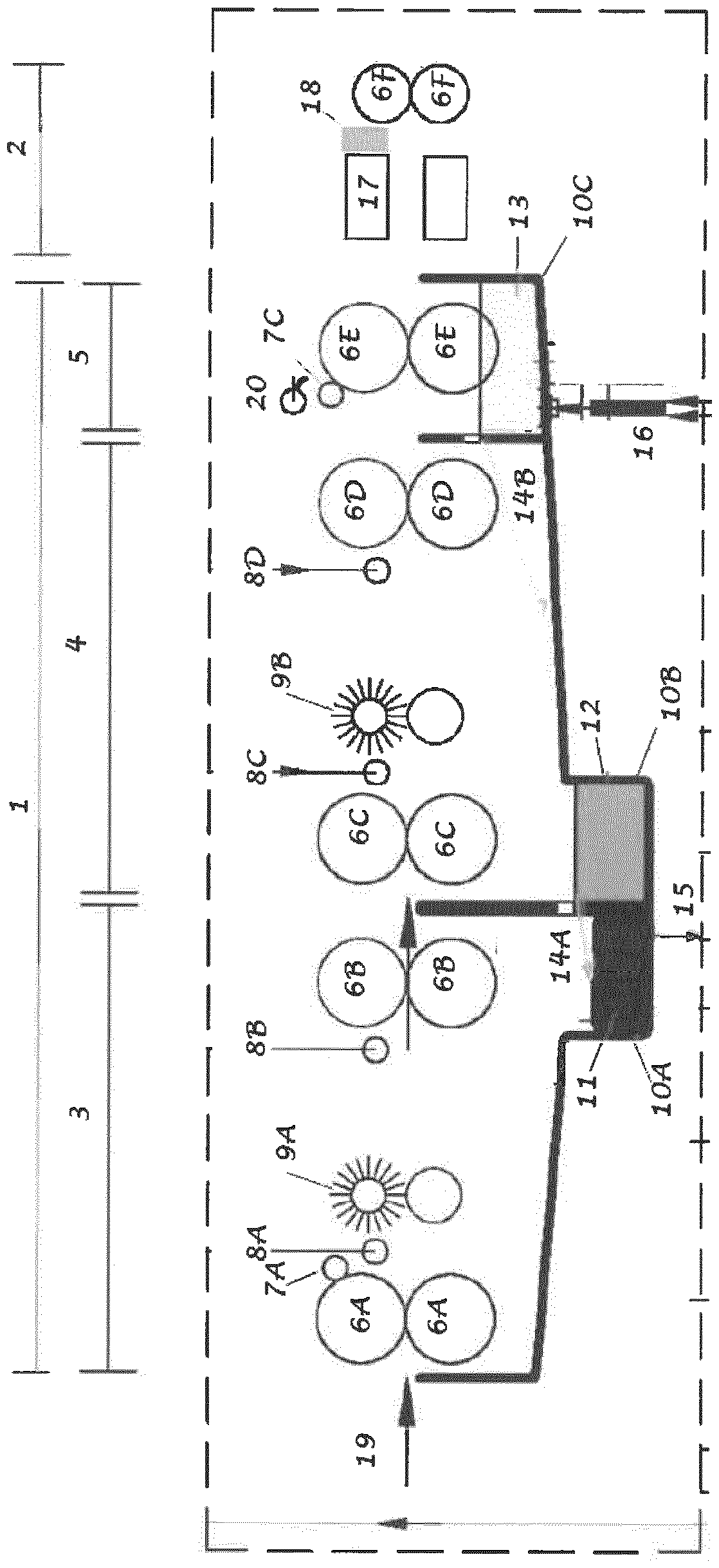
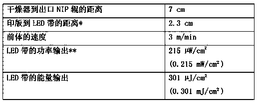

Image

  • A method for making a lithographic printing plate
  • A method for making a lithographic printing plate
  • A method for making a lithographic printing plate

Examples


Embodiment

[0139] All materials used in the following examples were readily purchased from standard sources such as Sigma-Aldrich (Belgium) and Acros (Belgium) unless otherwise indicated.

[0140] Preparation of aluminum carrier S-01

[0141] Aluminum foils of 0.3 mm thickness were degreased by spraying with an aqueous solution containing 26 g / l NaOH for 2 s at 65 °C and rinsed with demineralized water for 1.5 s. Then at a temperature of 37°C and about 100 A / dm 2 At a current density of 15 g / l HCl, 15 g / l SO 4 2- ions and 5 g / l Al 3+ The foil was electrochemically grained within 10 seconds using an alternating current in an aqueous solution of ions. The foils were then descaled by etching with an aqueous solution containing 5.5 g / l NaOH for 2 seconds at 36°C and rinsed with demineralized water for 2 seconds. followed by a temperature of 50°C and 17 A / dm 2 The foil was anodized for 15 seconds in an aqueous solution containing 145 g / l sulfuric acid at a current density of 15 s, then ...


PUM

PropertyMeasurementUnit
wavelengthaaaaaaaaaa
surface roughnessaaaaaaaaaa

Abstract

A method for making a negative-working lithographic printing plate is disclosed which includes subjecting an image-wise exposed, developed and dried plate precursor to UV LED radiation.

Description

[0001] technical field [0002] The present invention relates to a new method of manufacturing lithographic printing plates. Background technique [0003] Lithographic printing usually involves the use of so-called printing masters, such as printing plates mounted on the cylinders of a rotary printing press. The master bears a lithographic image on its surface, and the print is obtained by applying ink to the image, followed by transfer of the ink from the master to a printing substrate, usually paper. In conventional lithography, ink is supplied with an ink fountain solution (also known as fountain solution) to areas composed of oleophilic (or hydrophobic, that accepts ink but repels water) and hydrophilic (or oleophobic, that accepts water and repels water) areas. A lithographic image composed of areas of ink). In so-called offset printing, the lithographic image consists of ink-accepting and ink-repelling (ink-repelling) areas, and during offset printing only ink is s...

Claims


Application Information

Patent Timeline
Patent Type & Authority Applications(China)
IPC IPC(8): G03F7/40G03F7/20
CPCG03F7/2024G03F7/40
Inventor P.亨德里克斯K.希姆斯舒特S.韦布吕格
Owner 易客发有限公司
Learn More