
QPD image post-processing method and QPD camera

A post-processing and image technology, applied in the field of image processing, can solve the problems of poor quality of foreground target mask, small range, and unavailability of internal details of objects in the image, so as to improve the effect of image post-processing and performance.

Pending Publication Date: 2021-03-19
豪威科技(武汉)有限公司
View PDF7 Cites 1 Cited by
  • Summary
  • Abstract
  • Description
  • Claims
  • Application Information

AI Technical Summary

Problems solved by technology

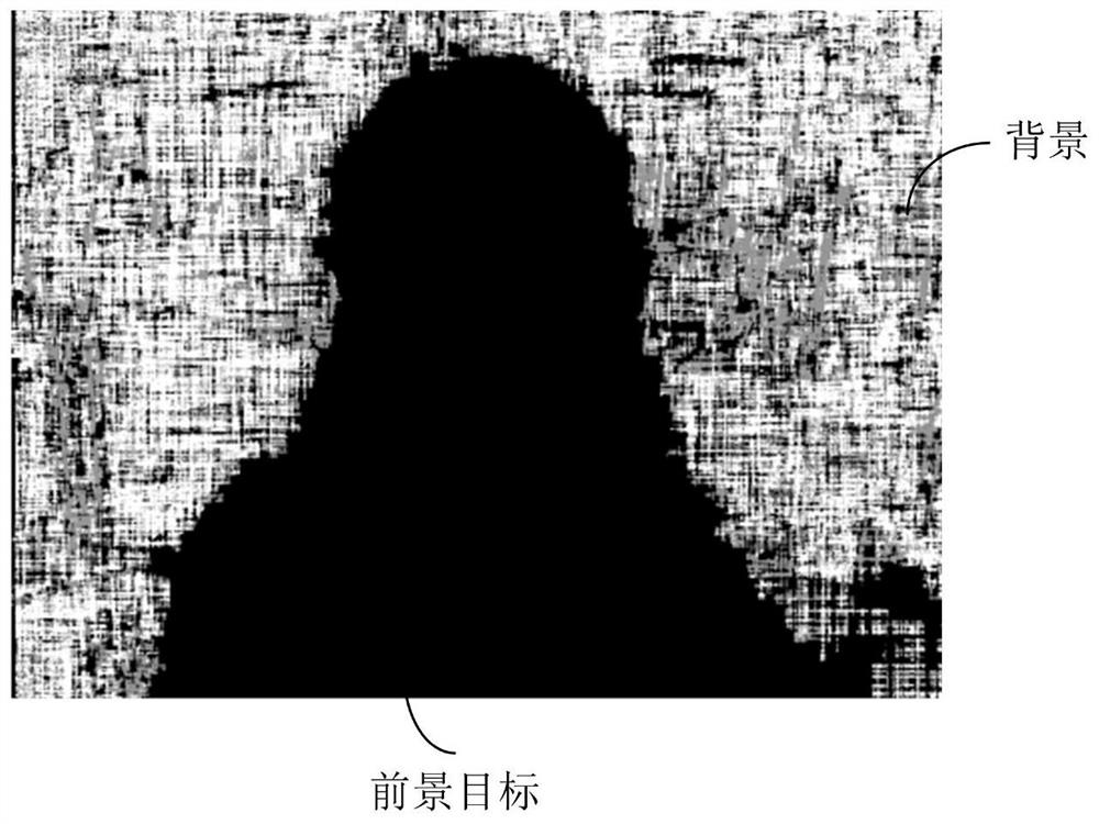
Since the focal plane parallax of the four-way sub-image obtained by splitting the QPD original image is 0, the pre-focus parallax is less than 0, and the post-focus parallax is greater than 0, and the range of the parallax distribution is very small, such as figure 2 As shown, there are more holes in the disparity map obtained by sub-image processing using the existing method, and the measured noise data is also more, and the internal details of the object in the picture are not available, resulting in inaccurate boundaries of foreground objects based on the disparity map. , so that the quality of the foreground target mask obtained is poor. If the foreground target mask is used for image post-processing such as background blur, the effect of image post-processing is poor, and the quality of the obtained target image is poor.
Currently common devices such as binocular vision devices obtain disparity maps with low noise, sharp boundaries, and excessive flatness. Therefore, existing disparity map post-processing strategies such as joint weighted median filtering, joint superpixel segmentation, constrained smoothing, and regional mismatching are not applicable. Post-processing of disparity maps for QPD images

Method used


Image

  • QPD image post-processing method and QPD camera
  • QPD image post-processing method and QPD camera
  • QPD image post-processing method and QPD camera

Examples


Embodiment Construction

[0025] The QPD image post-processing method and the QPD camera proposed by the present invention will be further described in detail below in conjunction with the accompanying drawings and specific embodiments. The advantages and features of the present invention will become clearer from the following description. It should be noted that all the drawings are in a very simplified form and use imprecise scales, and are only used to facilitate and clearly assist the purpose of illustrating the embodiments of the present invention.

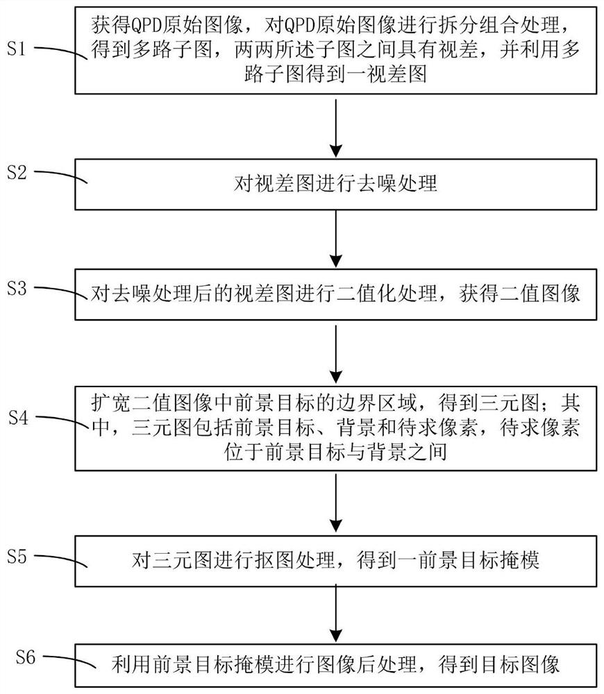
[0026] In order to obtain a high-quality foreground target mask from the QPD original image, this embodiment provides a QPD image post-processing method. image 3 It is a flowchart of a QPD image post-processing method according to an embodiment of the present invention. Such as image 3 As shown, the QPD image post-processing method includes:

[0027] S1. Obtain an original QPD image, split and combine the original QPD image to obtain multiple sub...


PUM


Abstract

The invention provides a QPD image post-processing method and a QPD camera. According to the method, after a QPD original image is obtained, the QPD original image is split and combined to obtain multiple paths of sub-images with parallax, the multiple paths of sub-images are utilized to obtain a parallax image, denoising processing and binarization processing are performed on the parallax image to obtain a binary image, and a boundary region of a foreground target in the binary image is broadened to obtain a ternary image. Matting processing is carried out on the ternary graph to obtain a foreground target mask, and image post-processing is carried out by using the foreground target mask. By utilizing the method, the sharp boundary of the foreground target can be obtained, so that a high-quality foreground target mask is obtained, and the image post-processing effect is improved. According to the QPD camera, a disparity map acquisition module, a denoising module, a binarization module, a ternary image acquisition module, an image matting module and an image processing module in the QPD camera are utilized, so that a high-quality foreground target mask can be obtained, and the image post-processing effect of the camera can be improved.

Description

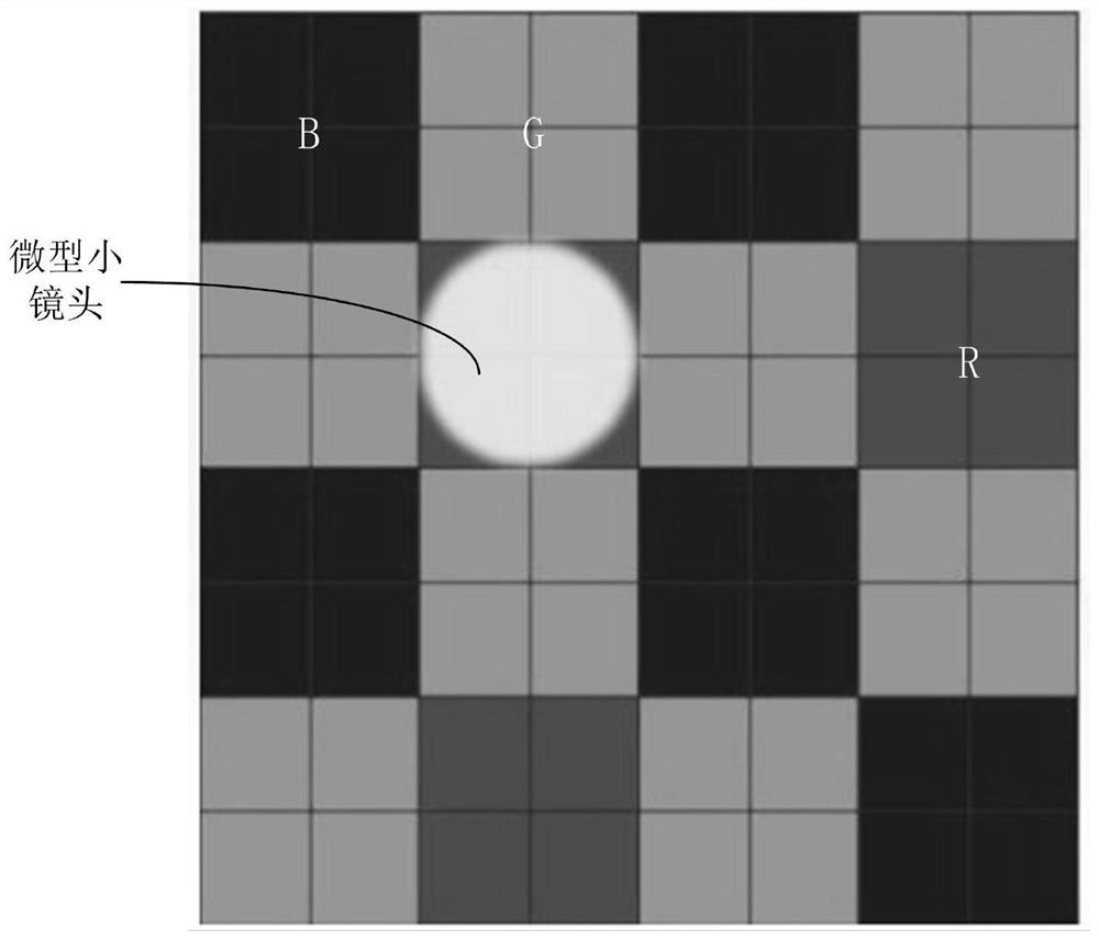
technical field [0001] The invention relates to the technical field of image processing, in particular to a QPD image post-processing method and a QPD camera. Background technique [0002] Background blur (Bokeh) of an image is an important shooting mode. For example, the front camera of a mobile phone often adopts the shooting mode of background blur. By blurring the background, the depth of field is shallowed and the focus of the image is on the subject. [0003] Currently, quad-phase pixel (QPD) technology has been applied to cameras because it enables higher-speed autofocus for camera devices (such as mobile phone cameras). [0004] figure 1 is a pixel structure diagram of a QPD image. Such as figure 1 As shown, in the original QPD image captured by a QPD (quad-phase pixel) camera, four adjacent pixels (each small square represents one pixel) share a micro lens, and the four adjacent pixels can use the same Color filters (eg red R, green G, blue B filters). The fou...

Claims


Application Information

Patent Timeline
Patent Type & Authority Applications(China)
IPC IPC(8): G06T3/00G06T5/00G06T7/12G06T7/155G06T7/194G06T7/593
CPCG06T7/12G06T7/155G06T7/194G06T7/593G06T2207/10024G06T3/04G06T5/70
Inventor 彭莎苏文凯
Owner 豪威科技(武汉)有限公司
Learn More