Screen stapling machine and working method thereof

A technology of net machine and stapler, which is applied in the field of net nailing machines, can solve the problems of affecting the retrieving effect, high waste rate, and decreased adhesive tape viscosity, and achieves adjustable filter mesh overlap, short nailing cycle, and cost saving Effect

Pending Publication Date: 2020-07-24
淄博智维自动化科技有限公司
View PDF0 Cites 0 Cited by
  • Summary
  • Abstract
  • Description
  • Claims
  • Application Information

AI Technical Summary

Problems solved by technology

[0004] (1) The cone mesh machine needs to manually cut the filter screen into fan-shaped mesh, and then nail each mesh at a time. The cost of fan-shaped mesh is high, and multiple meshes will be caused by static electricity, burrs, etc. Sticking together, affecting device stability
[0005] (2) The reclaiming mechanism of the conical screen making machine is carried out by paper tape. Since the filter screen is made of glass fiber, many lint will stick to the paper tape, which will easily cause the viscosity of the tape to decrease and affect the reclaiming effect.
[0006] (3) The winding part of the conical mesh machine cannot be adjusted. When the type of filter needs to be replaced, the winding shaft needs to be replaced. The workload of replacing the winding shaft is very heavy, and it is not easy for the operator to operate.
[0007] (4) The structure of the winding part of the automatic net making machine is complex, and the long-term wear of the reel will affect the accuracy and stability of the equipment
[0008] (5) The retrieving part of the automatic screen making machine is easy to cause the filter screen to shift, and the scrap rate is high

Method used


Image

  • Screen stapling machine and working method thereof
  • Screen stapling machine and working method thereof
  • Screen stapling machine and working method thereof

Examples


Embodiment Construction

[0074] The present invention will be described in further detail below in conjunction with the accompanying drawings.

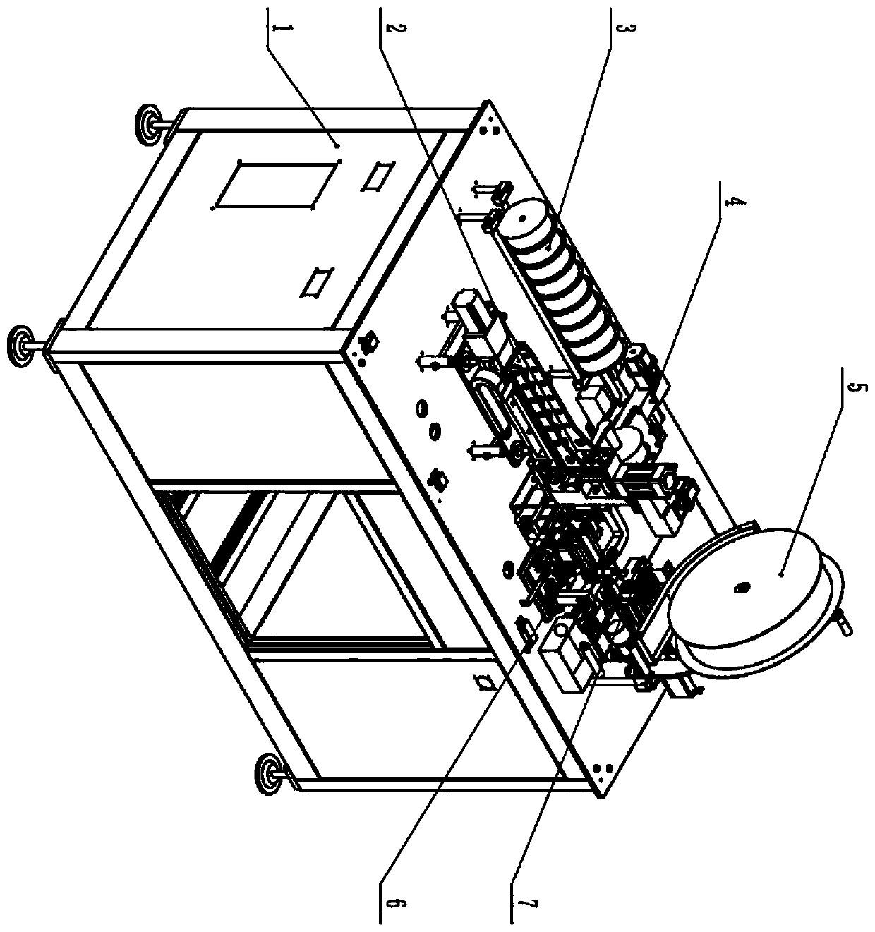
[0075] Such as figure 1 As shown, a nailing machine includes: a frame 1, and the frame 1 is all made of aluminum alloy, which greatly reduces the weight of the equipment and has a beautiful appearance. The filter screen hopper 5 arranged on the frame 1 is used to place the rolled filter screen 101. When a roll of filter screen 101 is used up, it can be replaced quickly for easy operation; Net assembly 7, it is used to cut filter screen 101 into rectangular filter screen sheet 102; The filter screen transfer assembly 4 that is arranged on the frame 1, it is used for filter screen sheet 102 is moved to roll net from net cutting assembly 7 Component 6; the rolling net component 6 arranged on the frame 1, which is used to roll the filter screen sheet 102 into a filter screen cylinder 103; the stapler assembly 2 arranged on the frame 1, which is used to filter the ...


PUM


Abstract

The invention relates to a screen stapling machine and a working method thereof. The screen stapling machine includes a rack, a filter screen bin, a screen cutting assembly, a filter screen transfer assembly, a screen rolling assembly and a stapler assembly; the filter screen bin is arranged on the rack and used for containing a coiled filter screen; the screen cutting assembly is arranged on therack and used for cutting the filter screen into a rectangular filter screen piece; the filter screen transfer assembly is arranged on the rack and used for moving the filter screen piece from the screen cutting assembly to the screen rolling assembly; the screen rolling assembly is arranged on the rack and used for rolling the filter screen piece into a filter screen cylinder; and the stapler assembly is arranged on the rack and used for stapling the filter screen cylinder. The screen stapling period is short. The coiled filter screen is used by the device and is automatically cut, and the cost is low. The specification of the filter screen can be adjusted at any time conveniently. The rolled screen is simple in structure and high in precision. Fewer filter screens are needed, and thus the cost is saved.

Description

technical field [0001] The invention relates to the technical field of hub manufacturing, in particular to a nailing machine and a working method thereof. Background technique [0002] The die-casting machine must place a filter screen to the liquid port of the mold before each casting of the wheel hub blank. The traditional nail filter screen is artificially nailed, which has low work efficiency and high labor intensity. With the development of the company's production, it is urgent to develop a set of equipment that can automatically nail the filter screen, reduce the labor intensity of the operator, and improve the automation of equipment production. [0003] Existing two kinds of prior art that are close to this patent, one is a conical mesh net making machine, and another is an automatic net making machine. But it has the following disadvantages: [0004] (1) The cone mesh machine needs to manually cut the filter screen into fan-shaped mesh, and then nail each mesh at...

Claims


Application Information

Patent Timeline
IPC IPC(8): B29C69/00B26D1/08B26D5/12B26D7/02B26D7/06B29C53/04B29C53/80B29C65/56B29L31/14
CPCB26D1/08B26D5/12B26D7/02B26D7/06B29C53/04B29C53/8008B29C53/8016B29C65/56B29C69/001B29L2031/14
Inventor 杨卫国李洋周国刘建秦华
Owner 淄博智维自动化科技有限公司
Why Eureka
Try Eureka