
Sand mixing device for casting machine

A technology of foundry machinery and sand mixing, which is applied to the cleaning/processing machinery of casting materials, casting molding equipment, manufacturing tools, etc. problems, to achieve the effect of improving rolling efficiency, reducing settings, and saving equipment space

Active Publication Date: 2020-07-28
YULIN UNIV
View PDF7 Cites 2 Cited by
  • Summary
  • Abstract
  • Description
  • Claims
  • Application Information

AI Technical Summary

Problems solved by technology

[0002] The sand mixer is a device that uniformly mixes the components in the molding sand and effectively coats the binder on the surface of the sand grains. Using the relative movement of the grinding wheel and the grinding plate, the materials placed between the two are rolled and ground. The effect of crushing materials, the sand mixer will also mix the materials while crushing the materials. In the existing sand mixing device, the rotating disc needs a special power mechanism, resulting in a complex structure, and the rotating speed of the rotating disc cannot be adjusted according to the usage conditions. , the initial rotating disc rotates too fast, the rolling effect is poor, resulting in waste of energy, and the later rotating disc rotates slowly, resulting in low rolling efficiency, which cannot meet the actual needs, so we invented a sand mixing device for foundry machinery

Method used


Image

  • Sand mixing device for casting machine
  • Sand mixing device for casting machine
  • Sand mixing device for casting machine

Examples


Embodiment Construction

[0014] In order to make the purpose, technical solutions and advantages of the embodiments of the present invention clearer, the technical solutions in the embodiments of the present invention will be clearly and completely described below in conjunction with the drawings in the embodiments of the present invention. Obviously, the described embodiments It is a part of embodiments of the present invention, but not all embodiments. Based on the embodiments of the present invention, all other embodiments obtained by persons of ordinary skill in the art without creative efforts fall within the protection scope of the present invention.

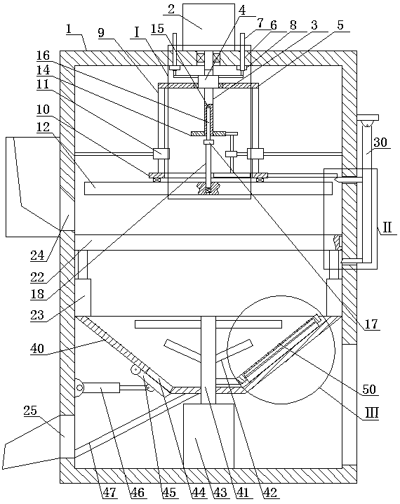
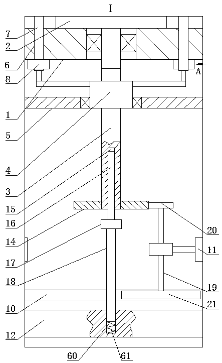
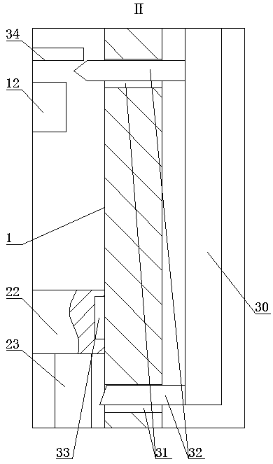
[0015]A sand mixing device for foundry machinery, as shown in the figure, includes a casing 1, the casing 1 is a hollow cylinder, the top side of the casing 1 is fixedly installed with a first motor 2, and the lower end of the first motor 2 shaft passes through The top side of the housing 1 is located at the upper end of the housing 1 and is fixed...


PUM


Abstract

A sand mixing device for a casting machine comprises a shell. A first motor is fixedly mounted on the top side of the shell, the lower end of a rotating shaft of the first motor penetrates through thetop side of the shell and is located in the shell to be fixedly connected with the upper end of a lead screw, the upper end of a vertical shaft is fixedly provided with a second small gear in meshingfit with a first large gear, the lower end of the vertical shaft is fixedly provided with a second large gear capable of being in meshing fit with a first small gear, and a feeding port and a discharging port are sequentially formed in the left side of the shell and located on the upper side and the lower side of a filter screen plate. The sand mixing device is simple in mechanism and ingenious in concept, a rotating grinding disc is driven to rotate by a driving device of a rotating grinding disc lifting mechanism, the arrangement of driving devices is reduced, the equipment space is saved,and the equipment production cost is reduced; and meanwhile, the rotating grinding disc can slowly rotate in the descending process, the rotating grinding disc can be prevented from being clamped by sand materials, the rotating grinding disc rotates automatically and rapidly when the sand materials are rolled, the grinding efficiency is improved, the market demand can be met, and the device is suitable for popularization.

Description

technical field [0001] The invention belongs to the field of sand mixing devices, in particular to a sand mixing device for foundry machinery. Background technique [0002] The sand mixer is a device that uniformly mixes the components in the molding sand and effectively coats the binder on the surface of the sand grains. Using the relative movement of the grinding wheel and the grinding plate, the materials placed between the two are rolled and ground. The effect of crushing materials, the sand mixer will also mix the materials while crushing the materials. In the existing sand mixing device, the rotating disc needs a special power mechanism, resulting in a complex structure, and the rotating speed of the rotating disc cannot be adjusted according to the usage conditions. , The initial rotating disc rotates too fast, the rolling effect is poor, resulting in waste of energy, and the later rotating disc rotates slowly, resulting in low rolling efficiency, which cannot meet th...

Claims


Application Information

Patent Timeline
IPC IPC(8): B22C5/04B22C5/06
CPCB22C5/04B22C5/044B22C5/06
Inventor 王筱冬牛艳君
Owner YULIN UNIV
Learn More