
Cutting apparatus and cutting tool trimming method

A cutting tool and cutting device technology, which is applied to fine working devices, parts of grinding machine tools, abrasive surface adjustment devices, etc., can solve problems such as long time and achieve the effect of efficient dressing

Pending Publication Date: 2020-07-28
DISCO CORP
View PDF6 Cites 0 Cited by
  • Summary
  • Abstract
  • Description
  • Claims
  • Application Information

AI Technical Summary

Problems solved by technology

Therefore, it may take a long time until the trimming is completed

Method used


Image

  • Cutting apparatus and cutting tool trimming method
  • Cutting apparatus and cutting tool trimming method
  • Cutting apparatus and cutting tool trimming method

Examples


Embodiment Construction

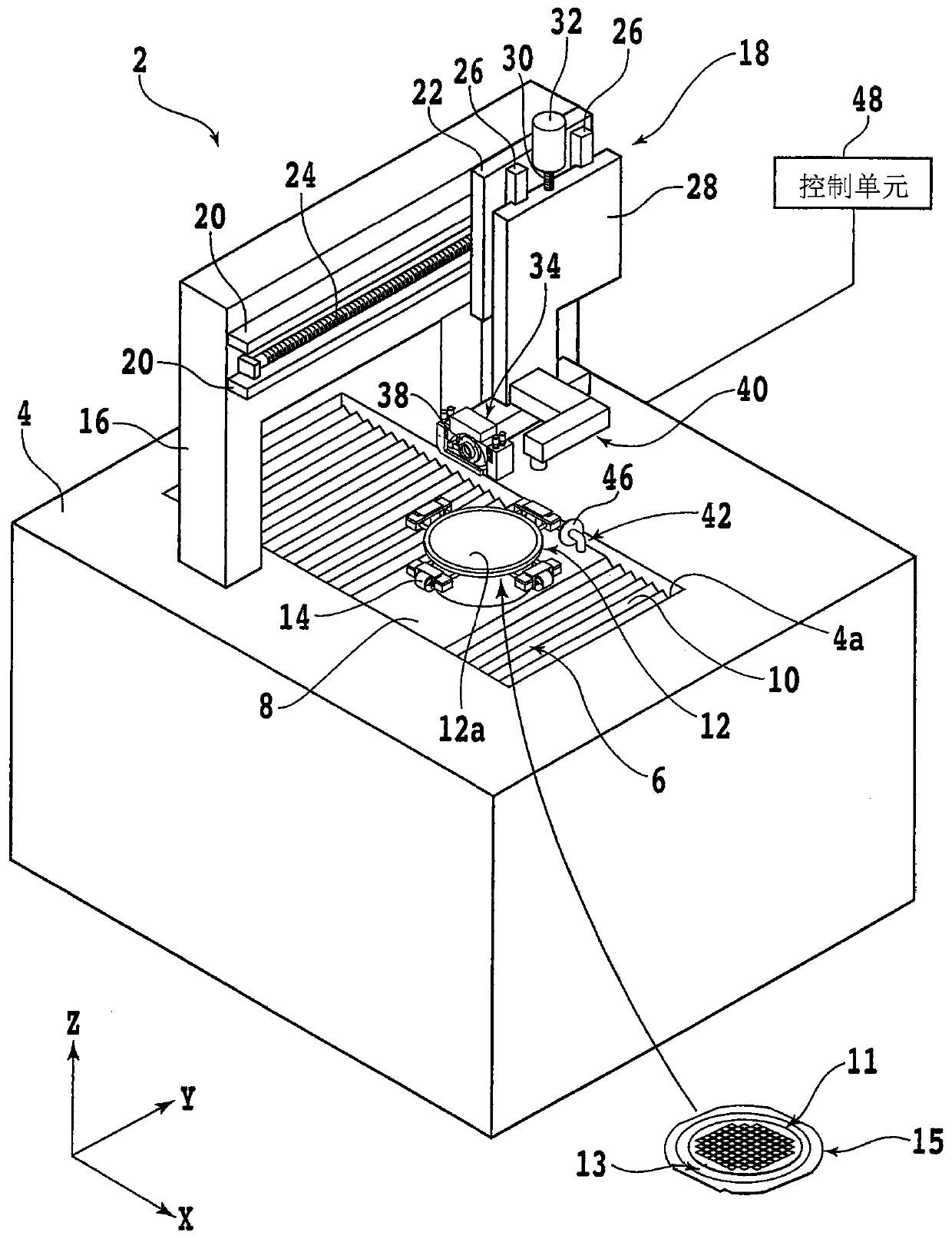
[0017] An embodiment of one embodiment of the present invention will be described with reference to the drawings. figure 1 It is a perspective view showing the cutting device 2 of this embodiment. Such as figure 1 As shown, the cutting device 2 has a base 4 that supports each component. An opening 4 a long in the X-axis direction (front-rear direction, machining feed direction) is formed on the upper surface of the base 4 .

[0018] A ball screw type X-axis moving mechanism (machining feed mechanism) 6 is arranged in the opening 4a. The X-axis moving mechanism 6 has an X-axis moving table (not shown), and moves the X-axis moving table in the X-axis direction. In addition, the X-axis moving mechanism 6 and the upper part of the X-axis moving table are covered with a table cover 8 and a corrugated cover 10 .

[0019] A chuck table (holding table) 12 for holding a plate-shaped workpiece 11 is arranged on the X-axis movable table so as to be exposed from the table cover 8 . T...


PUM

PropertyMeasurementUnit
diameteraaaaaaaaaa

Abstract

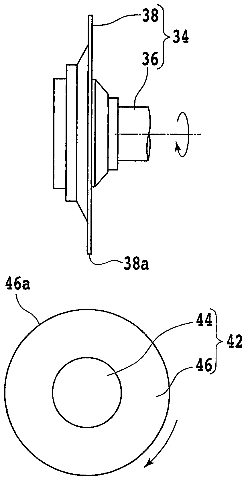
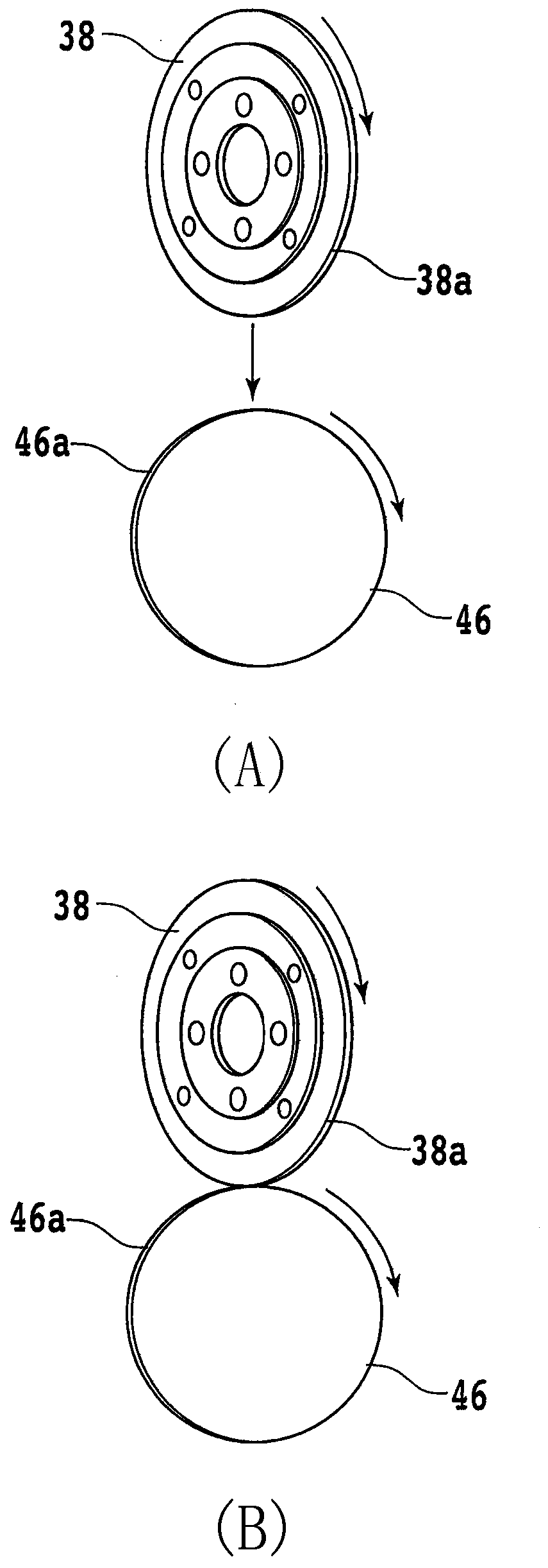
A cutting apparatus and a trimming method of a cutting tool are provided. The cutting tool can be efficiently trimmed in a short time. The cutting apparatus is used for cutting a plate-shaped workpiece, and the cutting apparatus comprises a holding table having a holding surface for holding the workpiece; a cutting unit having a rotating shaft to which a disc-shaped cutting tool having a cutting edge on the outer peripheral portion is attached, the cutting unit rotating the cutting tool together with the rotating shaft to cut the workpiece held by the holding table; a cutting mechanism that moves the cutting unit in a direction perpendicular to the holding surface; and a dressing unit having a rotating shaft to which a disc-shaped dressing plate is attached, the dressing unit dressing thecutting tool by rotating the dressing plate together with the rotating shaft, and the rotating shaft of the dressing unit being disposed non-parallel to the rotating shaft of the cutting unit.

Description

technical field [0001] The present invention relates to a cutting device for cutting a plate-shaped workpiece, and a dressing method of a cutting tool applied to the cutting device. Background technique [0002] There is known a processing method called edge trimming, which partially removes the outer periphery of a disk-shaped workpiece represented by a semiconductor wafer. In edge trimming, a ring-shaped cutting blade in which abrasive grains such as diamond are fixed with a bonding material such as metal is rotated to cut into the outer peripheral portion of the workpiece. [0003] At this time, only a part (for example, about 2 / 3 of the thickness direction) of the cutting tool is in contact with the outer peripheral portion of the workpiece. Therefore, during edge trimming, a part of the cutting tool that contacts the workpiece is worn, and minute steps and inclinations are generated on the outer peripheral surface of the cutting tool. [0004] The steps and inclinatio...

Claims


Application Information

Patent Timeline
Patent Type & Authority Applications(China)
IPC IPC(8): B28D5/02B24B27/06B24B53/14
CPCB28D5/022B24B27/06B24B27/0683B24B53/14
Inventor 小松淳
Owner DISCO CORP
Learn More