
Garbage treatment fermentation device

A technology for fermenting equipment and waste disposal, which is applied in the field of waste disposal and fermentation equipment, and can solve the problems of bending resistance, low torsional strength, overall dehydration device stuck, and potential safety hazards, and achieve low cost, low physical property requirements, and dehydration good effect

Pending Publication Date: 2020-07-28
中环怡美环境科技(浙江)有限公司
View PDF0 Cites 1 Cited by
  • Summary
  • Abstract
  • Description
  • Claims
  • Application Information

AI Technical Summary

Problems solved by technology

In the process of dehydrating various materials, especially vegetable waste, this type of dehydration device often contains a large amount of plastic binding ropes, long plant fibers and other entanglement substances after the workers have not thoroughly treated them. During the dehydration process, these substances can easily cause the port to be blocked, the end shaft to be entangled, affect the dehydration discharge, or even block the dehydration device as a whole, which will cause damage to the entire device and pose a safety hazard
[0003] At present, the stirring arm installed in the fermentation bin is usually rotated by the rotating shaft, and the stirring arm is prone to hit the wall under the action of centrifugal force
This type of mixing arm adopts a conventional three-claw structure. The mixing arm has low bending and torsional strength during operation. When there are too many materials in the bin, it is easy to cause problems such as weak mixing, and in severe cases, it will cause the machine to stop and be stuck.

Method used


Image

  • Garbage treatment fermentation device
  • Garbage treatment fermentation device
  • Garbage treatment fermentation device

Examples


Embodiment Construction

[0027] The present invention will be described in further detail below in conjunction with the accompanying drawings.

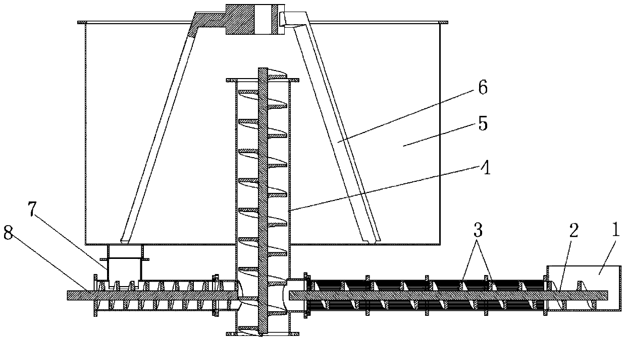
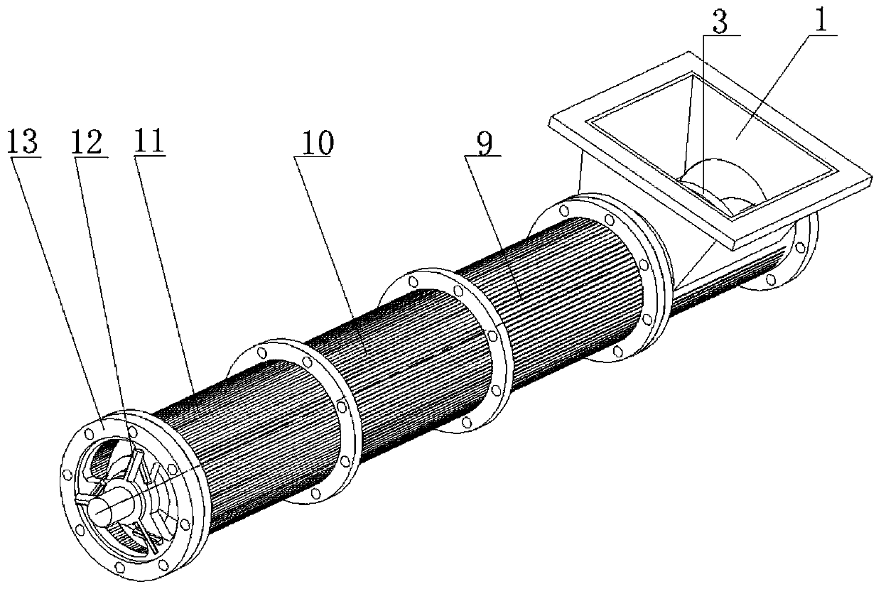
[0028] Such as Figure 1-Figure 6 A garbage treatment fermentation device shown includes a dehydration feeding device, a vertical feeding device 4, a circulating stirring device 6, a fermentation bin 5 and a circulating discharging device 8, the vertical feeding device includes a feeding cylinder 20, and the feeding The upper end of the cylinder is inserted into the fermentation chamber, and the center of the feeding cylinder is provided with a transmission shaft 19 that runs through the cylinder. The transmission shaft is provided with auger blades 21 from bottom to top, and the lower side of the feeding cylinder is A feed inlet is provided, and the feed inlet is connected to the outlet of the dehydration feeding device. The circulation stirring device is arranged in the fermentation chamber and includes a central rotating shaft 15, and a plurality of stirri...


PUM


Abstract

The invention relates to a garbage treatment fermentation device. The garbage treatment fermentation device comprises a dehydration feeding device, a vertical feeding device, a circulating stirring device, a fermentation bin and a circulating discharging device, wherein the vertical feeding device comprises a feeding cylinder body, the upper end of the feeding cylinder body is inserted into the fermentation bin, a transmission shaft penetrating through the cylinder body is arranged in the center of the feeding cylinder body, the transmission shaft is provided with auger blades from bottom to top, a feeding port is formed in one side of the lower part of the feeding cylinder body, the feeding port is in butt joint with an outlet of the dehydration feeding device, the circulating stirring device is arranged in the fermentation bin and comprises a central rotating shaft, the lower part of the central rotating shaft is connected with a plurality of stirring arms, the stirring arms are distributed in a multi-claw type structure, a discharging port is formed in the bottom of one side of the fermentation bin, and the discharging port is in butt joint with the circulating discharging device. The garbage treatment fermentation device is compact in overall equipment structure, the occupied area is reduced, the conveying is stable, and the dehydration and fermentation effects can be improved.

Description

technical field [0001] The invention relates to a garbage treatment fermentation device. Background technique [0002] The existing fermentation bin device in the field of garbage crushing and processing has a complex overall structure, and usually adopts a horizontal conveying structure, which takes up a large space and is expensive. The dehydration device generally includes a dehydration grid structure, and the gaps on the dehydration grid structure are usually evenly arranged, and there is no change in the direction from the inlet to the outlet, and the dehydration effect is average. In the process of dehydrating various materials, especially vegetable waste, this type of dehydration device often contains a large amount of plastic binding ropes, long plant fibers and other entanglement substances after the workers have not thoroughly treated them. During the dehydration process, these substances can easily cause the port to be blocked, the end shaft to be entangled, affe...

Claims


Application Information

Patent Timeline
Patent Type & Authority Applications(China)
IPC IPC(8): B30B9/14B02C18/14B02C18/18B09B3/00B09B5/00
CPCB30B9/14B02C18/0092B02C18/14B02C18/18B09B5/00B02C2201/06B09B3/40
Inventor 梁海臣范振兴陈自军潘志勇
Owner 中环怡美环境科技(浙江)有限公司
Learn More