Steel plate-concrete composite shear wall and connecting structure thereof and construction method thereof

A combination of shear wall and steel plate concrete technology, which is applied in the direction of walls, building components, building structures, etc., can solve the problems that the prefabricated construction requirements cannot be realized, the quality of sleeve grouting is difficult to guarantee, and the amount of steel used in shear walls is large. , to avoid the exposure of the interface, meet the aesthetic requirements, and achieve good ductility

Pending Publication Date: 2020-07-28
渝建实业集团股份有限公司
View PDF0 Cites 3 Cited by
  • Summary
  • Abstract
  • Description
  • Claims
  • Application Information

AI Technical Summary

Problems solved by technology

[0005] In view of the above-mentioned deficiencies existing in the prior art, the purpose of the present invention is to solve the problems of the existing shear walls such as large amount of steel used, heavy wall weight, complicated installation, difficulty in guaranteeing the quality of sleeve grouting, and inability to meet the requirements of prefabricated construction, etc., and provide a A steel plate concrete composite shear wall and its connection structure and construction method give full play to the advantages

Method used


Image

  • Steel plate-concrete composite shear wall and connecting structure thereof and construction method thereof
  • Steel plate-concrete composite shear wall and connecting structure thereof and construction method thereof
  • Steel plate-concrete composite shear wall and connecting structure thereof and construction method thereof

Examples


Example Embodiment

[0041] Examples:

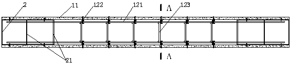
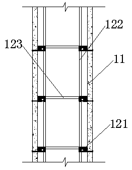
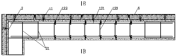
[0042] See Figure 1-Figure 5 , A steel plate-concrete composite shear wall, comprising a wall 1 and an edge member 2. The wall 1 and the edge member 2 integrally form a composite wall leg, and the composite wall leg is filled with concrete. The wall 1 includes two side templates 11 and a reinforcing steel frame 12 located between the two side templates 11. The reinforcing steel frame 12 is fixed to the two side templates 11 through connecting pieces. The reinforcing steel skeleton 12 includes horizontally distributed ribs 121, vertical distributed ribs 122, and web bars 123. There are two horizontally distributed ribs 121 located on the same horizontal plane, and the web bars 123 are distributed at two intervals along the length of the horizontally distributed bars 121. There are several horizontally distributed ribs 121, and the two ends of the web member 123 are welded and fixed to the two horizontally distributed ribs 121 respectively, so as to ensure the ...


PUM


Abstract

The invention discloses a steel plate-concrete composite shear wall and a connecting structure thereof and a construction method thereof. The steel plate-concrete composite shear wall comprises a wallbody and edge members; the wall body comprises two side templates and a steel reinforcement framework positioned between the two side templates; the steel reinforcement framework comprises horizontally distributed ribs, vertically distributed ribs and web members; the edge members are of tubular structures with one open sides; a plurality of batten plates are arranged in the edge members; two edge members are arranged and positioned between the two side templates; the two ends of the horizontally distributed ribs of the steel reinforcement framework correspondingly extend into the edge members from the gaps between the two adjacent batten plates of the adjacent edge members; the wall body and the edge members integrally form a combined wall column; and the combined wall column is filled with concrete. According to the steel plate-concrete composite shear wall, an assembled steel plate-concrete composite shear wall is mainly precast in the factory, and therefore, the wall body structure is simple, the force transmission is obvious, the assembled steel plate-concrete composite shear wall can be suitable for shear wall structural systems, frame-shear wall structural systems, and theapplication prospect is good.

Description

Technical field [0001] The invention relates to the technical field of construction, in particular to a steel plate concrete composite shear wall, its connection structure and a construction method. Background technique [0002] The construction of the existing concrete shear wall structure requires on-site reinforcement, tying of steel bars, and supporting formwork. After the concrete is poured, it takes a certain period of time to maintain the formwork before it can be removed. The operation is complicated, the site is wet and mainly depends on manual labor. Both the workload of on-site connection of steel bars and the workload of cast-in-place are relatively large, and there is also the problem that the connecting rods are not easy to install. Therefore, the on-site construction of shear walls is difficult, the quality is difficult to guarantee, and it is easy to cause safety and quality risks. [0003] As my country’s demographic dividend is gradually disappearing, labor costs ...

Claims


Application Information

Patent Timeline
IPC IPC(8): E04B2/86
CPCE04B2/8629
Inventor 肖基成田春雨陈琨江世永夏双武
Owner 渝建实业集团股份有限公司
Why Eureka
Try Eureka