Waste heat boiler leakage detection method and device
A waste heat boiler and leak detection technology, applied in the direction of steam boilers, steam boiler accessories, steam boiler components, etc., can solve the problems of resource waste, safety accidents, increase the workload of maintenance and production shutdown, etc., and achieve a simple and efficient method. Easy-to-use effects
- Summary
- Abstract
- Description
- Claims
- Application Information
AI Technical Summary
Problems solved by technology
Method used
Image

Examples
Embodiment 1
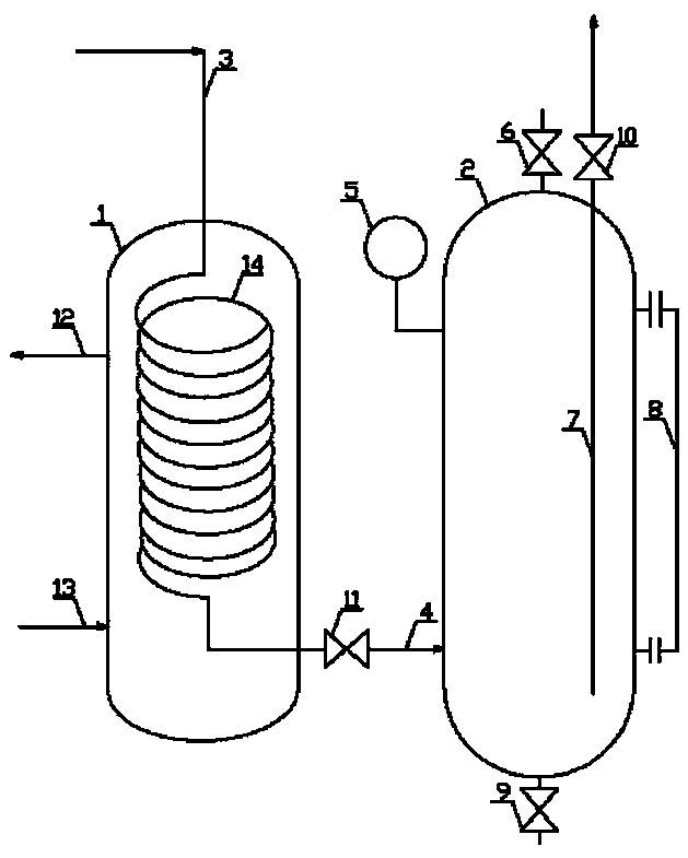
[0016] Embodiment 1: as attached figure 1 As shown, the waste heat boiler leakage detection method is carried out according to the following steps: first step, the sampling tank 1 and the liquid separation tank 2 are connected through the discharge pipeline 4, and after the connection, the discharge valve 11, the liquid discharge valve 10, The gas sampling valve 6 closes the drain valve 9; in the second step, the steam produced by the waste heat boiler enters the sampling tank 1 through the steam sampling line 3 of the waste heat boiler, and the steam is converted into condensate under the action of condensed water in the condensation pipe 14, and the condensate Enter the liquid separation tank 2 from the discharge pipeline 4; in the third step, the liquid level of the condensate in the liquid separation tank 2 continues to rise, record the amount of rising liquid level per unit time, and close the valve after the condensate flows out of the gas sampling valve 6 Gas sampling v...
Embodiment 2
[0018] Embodiment 2: as attached figure 1 As shown, the device of the waste heat boiler leakage detection method includes a sampling tank 1 and a liquid separation tank 2. The top of the sampling tank 1 is fixedly connected with a waste heat boiler steam sampling pipeline 3, and the outlet of the lower part of the sampling tank 1 is connected to the lower part of the liquid separation tank 2. There is a discharge pipeline 4 fixedly connected between the ports, a pressure gauge 5 is fixedly installed on the upper part of the liquid separation tank 2, a sampling port is installed on the top of the liquid separation tank 2, and a gas sampling valve 6 is fixedly installed on the sampling port, and the upper part of the liquid separation tank 2 is fixedly connected. There is a liquid discharge pipeline 7, the inlet of the liquid discharge pipeline 7 extends into the bottom of the liquid separation tank 2, a liquid level gauge 8 is fixedly installed on the side of the liquid separati...
Embodiment 3
[0019] Embodiment 3: as attached figure 1 As shown, as an optimization of the above embodiment, a drain valve 10 is fixedly installed at the outlet end of the drain line 7 .
PUM
 Abstract
Description
Claims
Application Information
 - R&D
- Intellectual Property
- Life Sciences
- Materials
- Tech Scout
- Unparalleled Data Quality
- Higher Quality Content
- 60% Fewer Hallucinations
Browse by: Latest US Patents, China's latest patents, Technical Efficacy Thesaurus, Application Domain, Technology Topic, Popular Technical Reports.
© 2025 PatSnap. All rights reserved.Legal|Privacy policy|Modern Slavery Act Transparency Statement|Sitemap|About US| Contact US: help@patsnap.com