Plate type condenser capable of discharging liquid in middle

A condenser and plate type technology, applied in the field of plate type condensers, to achieve the effect of reducing thickness, speeding up liquid discharge and evenly distributing

Active Publication Date: 2020-07-28
GUANGZHOU INST OF ENERGY CONVERSION - CHINESE ACAD OF SCI +1
View PDF10 Cites 3 Cited by
  • Summary
  • Abstract
  • Description
  • Claims
  • Application Information

AI Technical Summary

Problems solved by technology

But at present, this gas-liquid separation and condensation technology has only been studied in the tube-fin air condenser, and the research in the plate heat exchanger is still blank.

Method used


Image

  • Plate type condenser capable of discharging liquid in middle
  • Plate type condenser capable of discharging liquid in middle
  • Plate type condenser capable of discharging liquid in middle

Examples


Embodiment Construction

[0027] In order to make the above objects, features and advantages of the present invention more comprehensible, the present invention will be further described in detail below in conjunction with the accompanying drawings and specific embodiments.

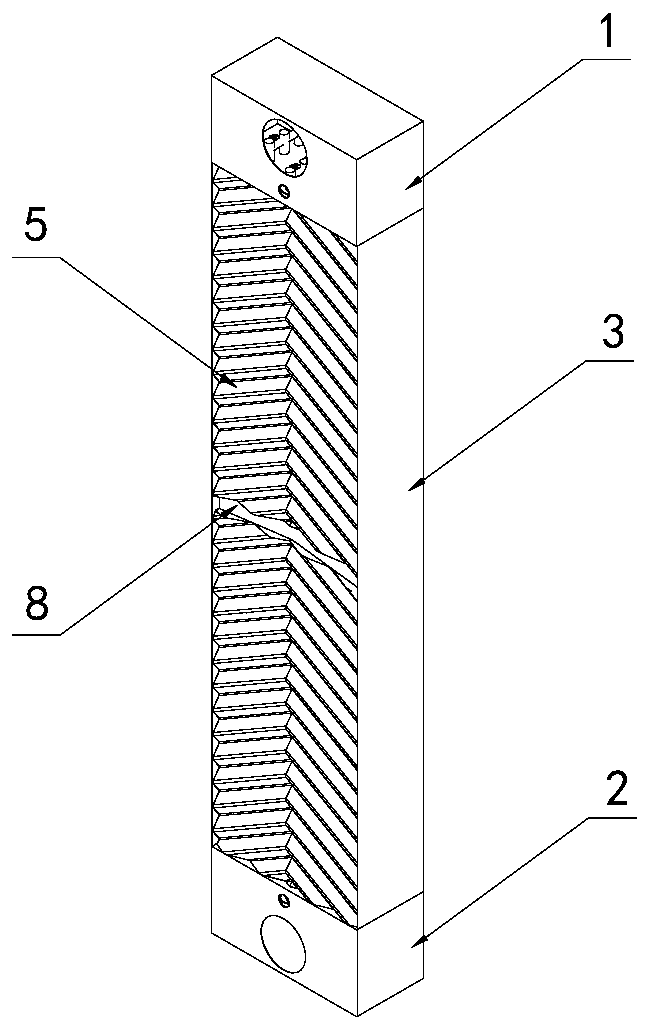
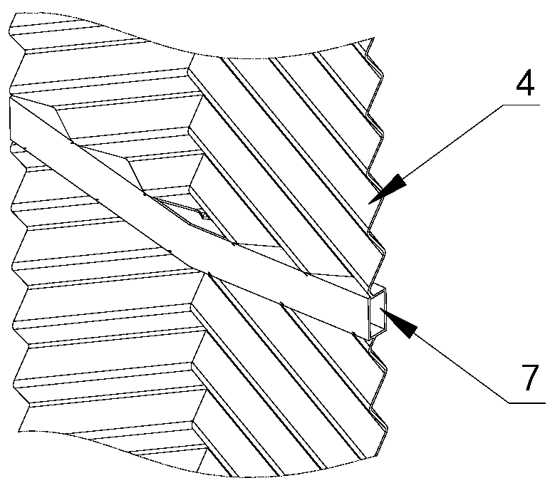
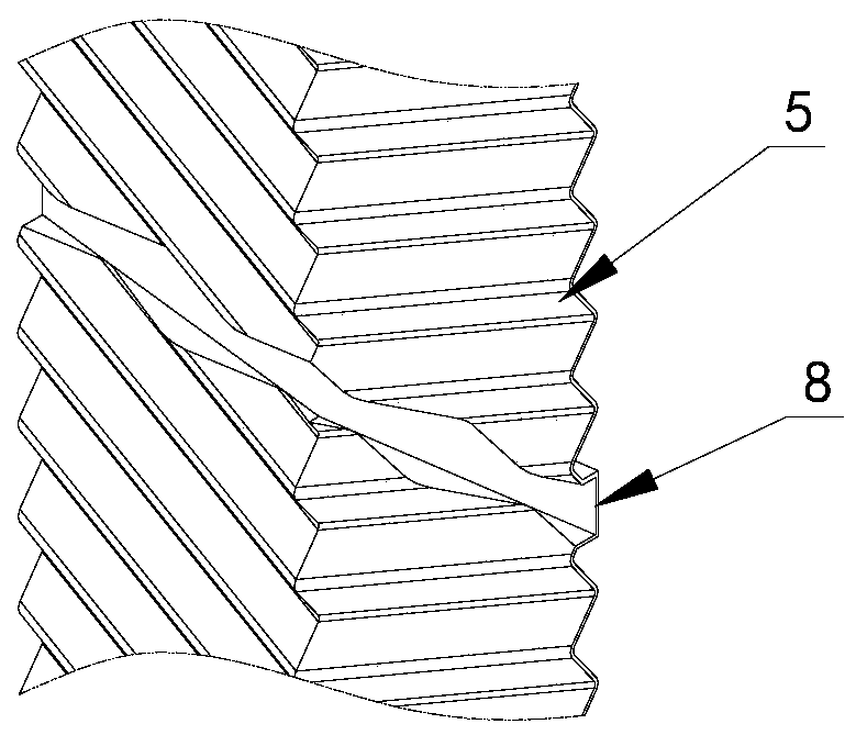
[0028] Such as Figure 1 to Figure 5 As shown, a plate condenser capable of draining liquid in the middle of this embodiment is mainly composed of an upper box body 1, a lower box body 2, a side sealing plate 3, an A-type heat exchange plate 4, a B-type heat exchange plate 5 and a middle Drainage pipe 6 forms. All parts can be made of plates and pipes through die stamping and welding processes, and the parts are connected together by brazing. The specific processing technology is the same as that of the current corrugated plate heat exchanger and will not be described in detail.

[0029] In this embodiment, 4 A-type heat exchange plates 4 and 5 B-type heat exchange plates 5 are alternately arranged to form 8 flow channels, of whi...


PUM


Abstract

The invention discloses a plate type condenser capable of discharging liquid in the middle. The plate type condenser comprises a plurality of type A heat exchange plates, a plurality of type B heat exchange plates, a pipe capable of discharging liquid in the middle, side sealing plates, an upper box body and a lower box body. The type A heat exchange plates and the type B heat exchange plates arealternately arranged to form steam flow channels and cooling water flow channels which are alternately arranged. The side sealing plates are connected to the two sides of a heat exchange plate row toseal the flow channels. The upper box body and the lower box body are connected to the upper end and the lower end of the heat exchange plate row respectively to form inlets and outlets of the steam flow channels and the cooling water flow channels. V-shaped gas-liquid separation cavities are formed in the middles of the type A heat exchange plates. Gas-liquid inlets are formed in the positions, located in the middles of the upper end faces of the steam flow channels, of the V-shaped gas-liquid separation cavities, and gas outlets are formed in the two ends of the lower end faces of the steamflow channels. The pipe capable of discharging liquid in the middle communicates with the bottom of each V-shaped gas-liquid separation cavity. According to the plate type condenser, the liquid discharging speed can be increased, the thickness of a condensate liquid film attached to a plate sheet is reduced, the heat conduction resistance of the liquid film is reduced, and the phase change heat transfer coefficient of the plate type condenser is increased.

Description

technical field [0001] The invention relates to the field of condensers, in particular to a plate condenser capable of intermediate draining. Background technique [0002] Plate heat exchanger is a heat exchange device with high heat transfer coefficient and compact structure, which has been widely used in liquid-liquid heat exchangers. Since the heat coefficient of phase change is much larger than that of non-phase change, using plate heat exchangers for condensation heat exchange is a development trend of current condensers. At present, most plate condensers directly use liquid-liquid plate heat exchangers. Different from the single-phase liquid convective heat transfer, the steam condensation heat transfer in the plate heat exchanger is a complex process in which the gas-liquid two-phase flow has both heat transfer and mass transfer in a small space. Due to the small distance between the plates of the plate heat exchanger, the structure of the flow channel is complex, an...

Claims


Application Information

Patent Timeline
Patent Type & Authority Applications(China)
IPC IPC(8): F28B9/04F28D9/00
CPCF28B9/04F28D9/00
Inventor 姚远龚宇烈王显龙刘雨兵陆振能曲勇
Owner GUANGZHOU INST OF ENERGY CONVERSION - CHINESE ACAD OF SCI
Why Eureka
Try Eureka