Design method of micro texture having flat wall surface drag reduction function

A design method and microtexture technology, applied in computer-aided design, design optimization/simulation, calculation, etc., can solve the problems of large amount of simulation, high cost, and no theoretical basis for design parameters.

Pending Publication Date: 2020-07-28
NANJING UNIV OF AERONAUTICS & ASTRONAUTICS
View PDF0 Cites 10 Cited by
  • Summary
  • Abstract
  • Description
  • Claims
  • Application Information

AI Technical Summary

Problems solved by technology

[0003] Although micro-textured drag reduction has been developed for decades, some scholars have summarized some drag reduction theories, such as protrusion height theory, secondary vortex group theory, air bearing theory, etc., but no unified theoretical explanation has been formed.
Although the drag-reducing micro-textured surface has broad application prospects, there is no universal drag-reducing micro-texture design method as a theoretical support, which limits its development.
[0004] At present, the design of flat wall drag-reducing micro-texture mostly adopts the method of numerical simulation, but there is no theoretical basis for the design parameters. In order to determine the surface micro-texture with drag-reducing effect, a large amount of simulation is required, which takes a long time and costs high. And the design result is not necessarily ideal

Method used


Image

  • Design method of micro texture having flat wall surface drag reduction function
  • Design method of micro texture having flat wall surface drag reduction function
  • Design method of micro texture having flat wall surface drag reduction function

Examples


Embodiment Construction

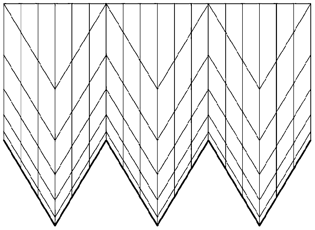
[0041] Designed for the drag-reducing micro-texture of the flat wall. First, the division of the boundary layer near the wall is analyzed to determine the action area of ​​the microtexture and calculate the thickness of this area. Secondly, the design range of size parameters and position parameters of the drag-reducing micro-texture is determined according to the dimensionless equation. Finally, computational fluid dynamics calculations are realized through finite element simulation to verify and optimize microtexture parameters.

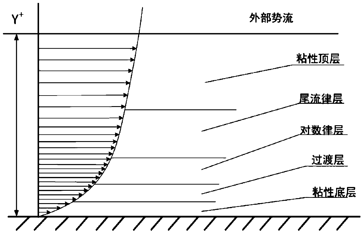
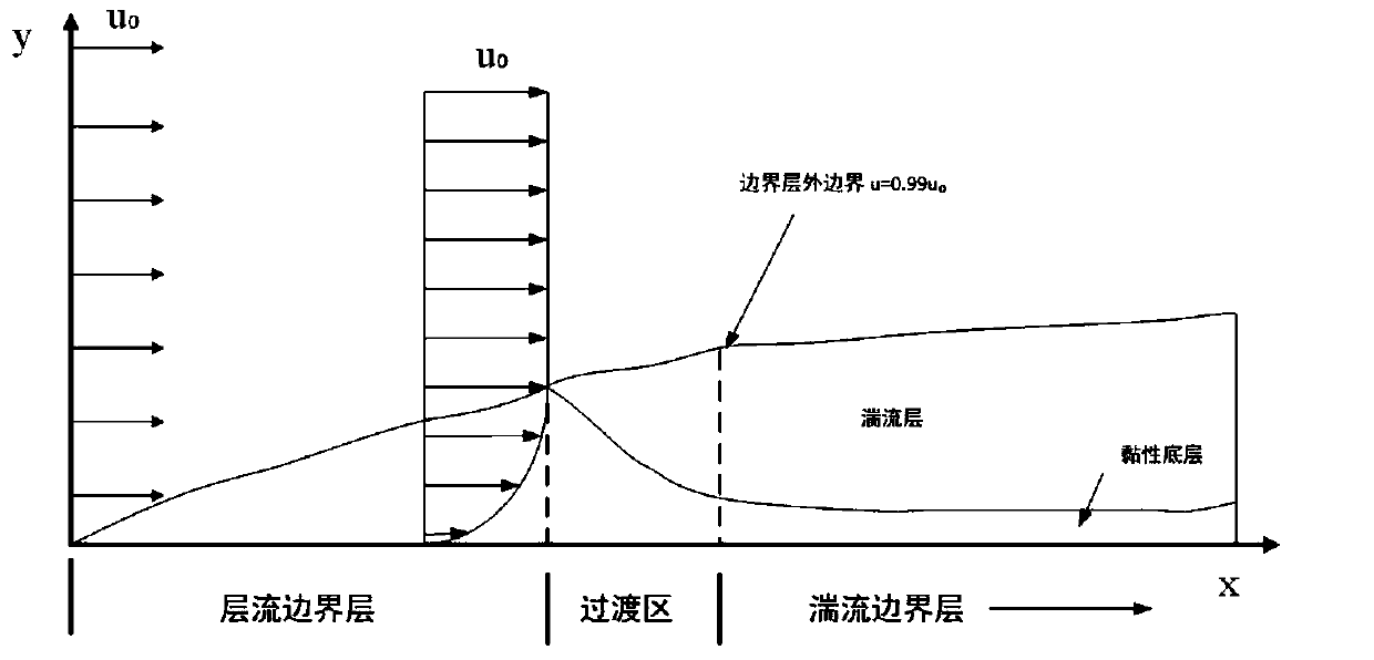
[0042] 1. Divide the boundary layer

[0043]According to Prandtl's boundary layer theory, in the flat wall turbulent flow, the boundary layer flow is laminar flow in front of the flat wall, and as the fluid continues to flow along the flat wall, the flow in the boundary layer transitions to turbulent flow . Divide the turbulent wall area into viscous bottom layer, buffer layer and logarithmic law layer, and make sure that the arrangement of tiny...


PUM


Abstract

The invention discloses a design method of a micro texture having a flat wall surface drag reduction function, and belongs to the field of surface texture design. According to the gas flow rate, an area, namely a buffer layer between a viscous bottom layer and a logarithmic law layer, where the wall shear stress is generated is determined by combining a boundary layer theory. Dimensionless treatment is performed on the size, and the thickness of the buffer layer is calculated so as to determine the height range of the micro texture. According to a Reynolds formula, the critical point of the fluid flowing from the laminar flow to the turbulent flow is calculated, and the arrangement area range of the micro texture is obtained. According to the two data, resistance reduction micro texture design is carried out, CREO software modeling is utilized, simulation is carried out through flow field simulation software FLUENT, the micro texture resistance reduction situation is analyzed, characteristic parameters of the micro texture are optimized, and the design of the flat-wall resistance reduction micro texture with the resistance reduction effect is achieved. The boundary layer theory isadopted, micro texture parameter design is conducted through layering and positioning of the turbulence area, the size design range of the drag reduction micro texture can be effectively narrowed, thesimulation amount is reduced, and the resource cost is saved.

Description

technical field [0001] The invention relates to a design method of a drag-reducing functional micro-texture on a flat wall surface, which can be used to improve the aerodynamic performance of a flat surface and reduce flow resistance, and belongs to the field of surface texture design. Background technique [0002] With the emergence of the global energy crisis, the loss of non-renewable resources, reducing energy waste, and exploring sustainable development have become important research topics. Due to the advancement of micro-nano measurement technology, people have gradually discovered that the special micro-nano structures on the surface of some organisms in nature can enable organisms to obtain some special properties. For example, the hydrophobicity and self-cleaning properties of the lotus leaf are derived from the tiny raised structures on its surface; the fast swimming ability of sharks in the water is attributed to the function of the downstream ribs on the skin su...

Claims


Application Information

Patent Timeline
Patent Type & Authority Applications(China)
IPC IPC(8): G06F30/23G06F30/28G06F113/08
Inventor 张臣徐琰
Owner NANJING UNIV OF AERONAUTICS & ASTRONAUTICS
Why Eureka
Try Eureka