Air inflow lip for turbojet nacelle

A technology of turbojet and engine, which is applied to the combustion of the intake port of the power plant, engine function, jet propulsion device, etc., and can solve the problems of difficult pipeline integration and difficult sealing

Pending Publication Date: 2020-07-28
SAFRAN NASEL
View PDF12 Cites 0 Cited by
  • Summary
  • Abstract
  • Description
  • Claims
  • Application Information

AI Technical Summary

Problems solved by technology

[0018] Integration of these ducts is difficult given the materials used to make cellular core structures such as "honeycomb" type structures
[0019] Also, the seal between the deicing fluid circulation ducts and the honeycomb foam core acoustic treatment structure is difficult to obtain

Method used


Image

  • Air inflow lip for turbojet nacelle
  • Air inflow lip for turbojet nacelle
  • Air inflow lip for turbojet nacelle

Examples


Embodiment Construction

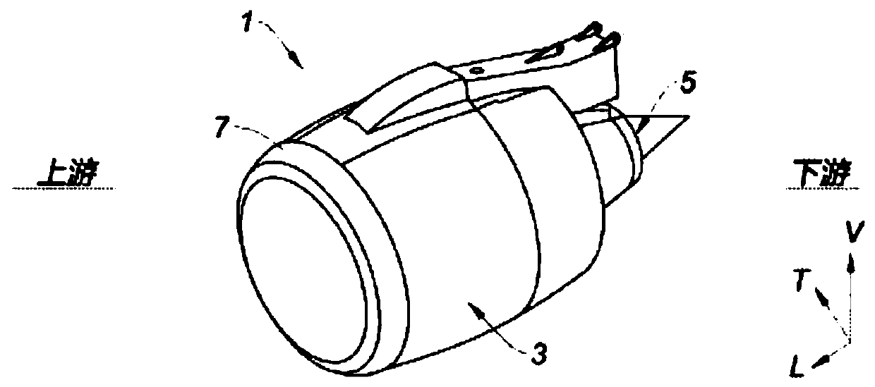
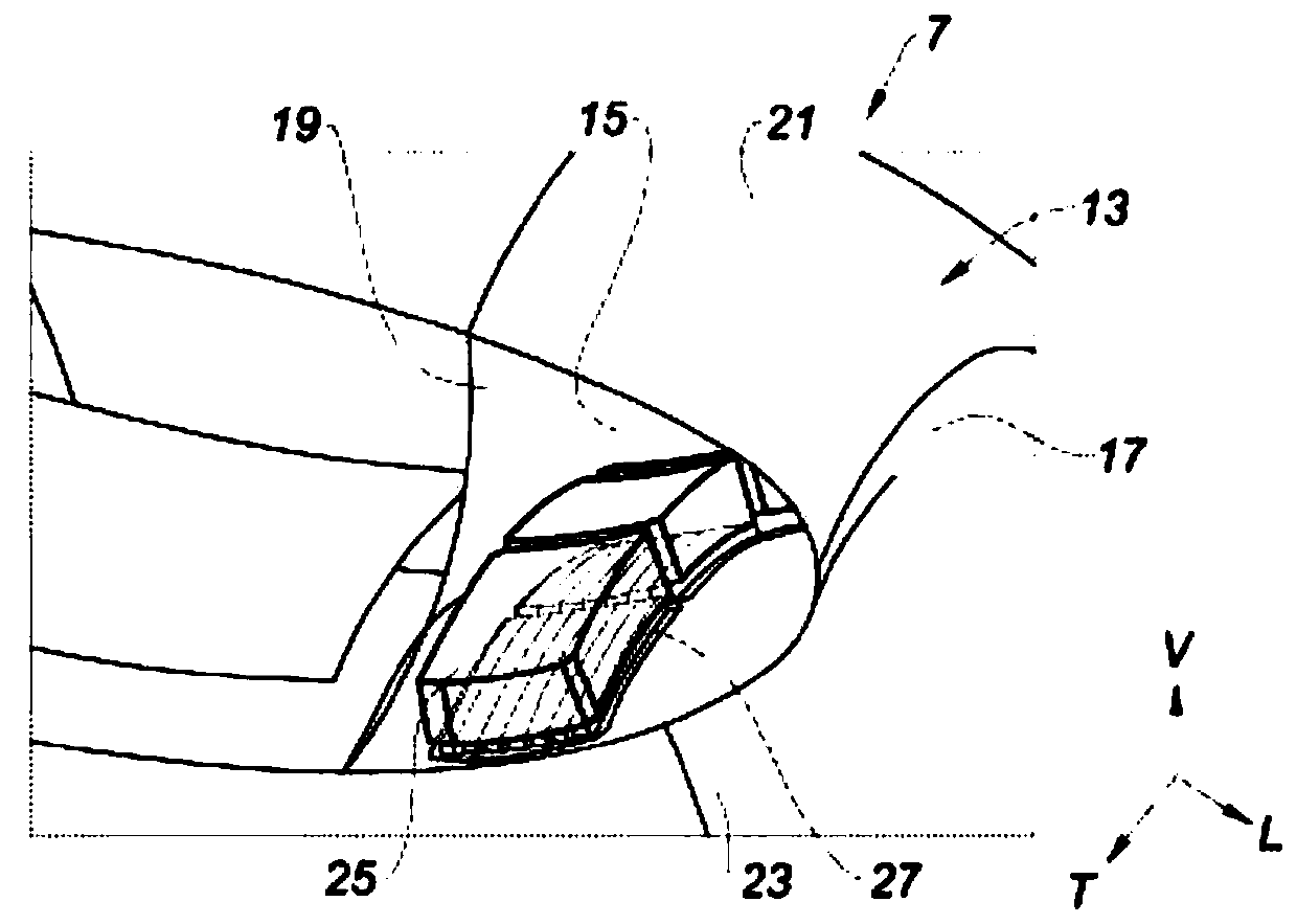
[0062] In the description and claims, the terms "upstream" and "downstream" are to be understood with respect to the circulation of the air flow inside the propulsion unit formed by the nacelle and the turbojet, that is to say with reference to figure 1 from left to right.

[0063] Likewise, the terms "inner" and "outer" will be used without limitation with reference to the radial distance relative to the longitudinal axis of the nacelle, the term "inner" defining the area radially closer to the longitudinal axis of the nacelle, the same as the term " External" on the contrary.

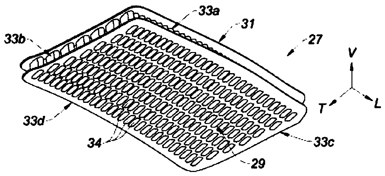
[0064] Furthermore, in the description and claims, the terms longitudinal, vertical and transverse will be used without limitation with reference to the trihedron L, V, T shown in the drawings for the purpose of clarifying the description and claims.

[0065] Furthermore, the same or similar reference numerals denote the same or similar components or component groups throughout the drawings.

[0066...


PUM

PropertyMeasurementUnit
Thicknessaaaaaaaaaa

Abstract

The invention relates to an air inflow lip of a nacelle for a turbojet of an aircraft, comprising a cavity defined by a leading edge of the nacelle and by an annular wall, said air inflow lip comprising: an inner wall (23); an acoustic treatment device; and a pneumatic de-icing device comprising a de-icing fluid supply device. The invention is characterised in that the inner wall (23) of the lip comprises a plurality of acoustic boreholes (28) and in that the pneumatic de-icing device comprises a honeycombed de-icing plate (27) mounted inside said cavity on said inner wall (23) of the lip andcomprising a plurality of conduits (35) for the circulation of a de-icing fluid and a plurality of acoustic wells communicating with said acoustic boreholes (28).

Description

technical field [0001] The invention relates to a nacelle air intake lip for an aircraft turbojet engine. Background technique [0002] Aircraft turbojet engines produce significant noise pollution. The need to aim to reduce this pollution is high, especially as the turbojet engines used are becoming more and more powerful. The design of the nacelle surrounding the turbojet contributes significantly to reducing this noise pollution. [0003] In order to further improve the acoustic performance of the aircraft, the nacelle has sound-absorbing panels, the purpose of which is to attenuate the noise produced by the turbojet engines. [0004] Usually, such acoustic panels are installed on the nacelle surrounding the turbojet at the inlet and / or outlet of the fan duct of the turbojet. [0005] Nacelles for aircraft turbojet engines often have multiple functions, such as directing airflow into and out of the engine, reversing the thrust of the turbojet engine, or even integratin...

Claims


Application Information

Patent Timeline
IPC IPC(8): B64D33/02B64D15/02
CPCB64D15/02B64D33/02F02C7/045F02C7/047B64D2033/0206B64D2033/0233B64C7/02F05D2220/32F05D2260/2214F05D2260/963
Inventor 帕特里克·博利奥卡洛琳·科阿-伦佐蒂马克·维尔萨维尔维吉妮·埃马纽埃尔·安妮·玛丽·迪吉奥斯皮埃尔-弗朗索瓦·贝哈格尔
Owner SAFRAN NASEL
Why Eureka
Try Eureka