Thoracic cavity drainage device for thoracic surgery department

A thoracic surgery and thoracic cavity technology, applied in the direction of suction containers, suction devices, hypodermic injection devices, etc., can solve the problems of interruption of drainage, troublesome replacement of drainage bottles, and influence on drainage effect, etc., and achieve the effect of practical function and novel structure

Inactive Publication Date: 2020-07-31
YANGZHOU FIRST PEOPLES HOSPITAL
View PDF0 Cites 1 Cited by
  • Summary
  • Abstract
  • Description
  • Claims
  • Application Information

AI Technical Summary

Problems solved by technology

[0003] In the process of performing thoracic surgery, the drainage volume is large, and sometimes it is necessary to replace the drainage bottle, but the replacement of the drainage bottle is troublesome, and the drainage will be interrupted during the replacement of the drainage bottle, which will affect the drainage effect

Method used


Image

  • Thoracic cavity drainage device for thoracic surgery department
  • Thoracic cavity drainage device for thoracic surgery department
  • Thoracic cavity drainage device for thoracic surgery department

Examples


Embodiment 1

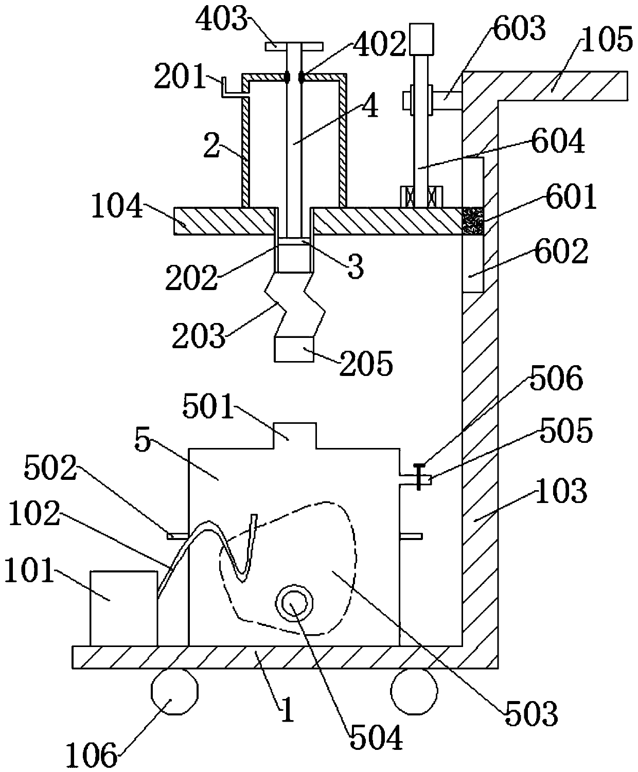
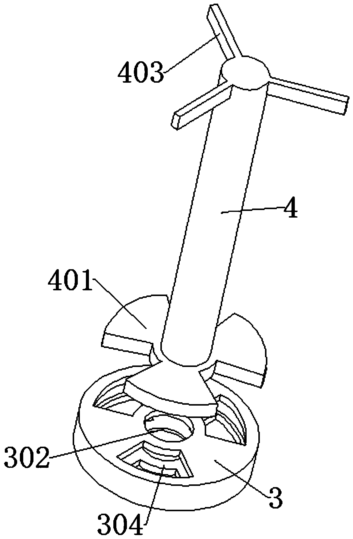
[0027] A chest drainage device for thoracic surgery, comprising a base plate 1, an auxiliary drainage barrel 2, a disc 3, a rotating shaft 4 and a main drainage barrel 5;

[0028] An air pump 101 is fixedly connected to the left side of the upper surface of the bottom plate 1, and an air-filling pipe 102 is fixedly connected to the air outlet of the air pump 101. A push rod 105 is fixedly connected to the top of the right side;

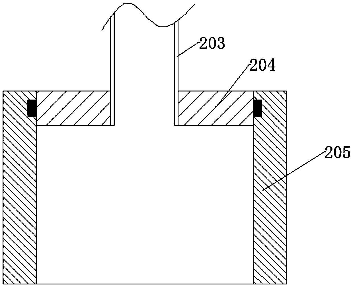
[0029] The auxiliary drainage barrel 2 is a cylindrical cavity structure with an open bottom, the bottom of the auxiliary drainage barrel 2 is fixedly connected to the upper surface of the connecting plate 104, the upper left side of the auxiliary drainage barrel 2 is fixedly connected with a liquid inlet pipe 201, and the connecting plate 104 A pipe 202 is fixedly connected to the center of the auxiliary drainage barrel 2, the bottom of the pipe 202 is fixedly connected to a bellows 203, the bottom of the bellows 203 is fixedly connected to a rotatin...

Embodiment 2

[0038] The difference from Example 1 is that it also includes the following:

[0039] The right side of the connecting plate 104 is longitudinally evenly fixed with a guide slider 601, the left side of the support plate 103 is provided with a guide chute 602 slidingly connected with the guide slider 601, and the left side of the support plate 103 above the connecting plate 104 is also fixed. A seat plate 603 is connected, and an adjusting screw 604 is engaged with the seat plate 603 , and the bottom of the adjusting screw 604 is rotatably connected with the upper surface of the connecting plate 104 .

[0040] A specific embodiment of the present invention is:

[0041] The height of the connecting plate 104 can be adjusted by adjusting the rotation of the screw rod 604 , so as to adjust the height of the auxiliary drainage barrel 2 and further adjust the height of the drainage.

[0042] Before performing drainage, first rotate the rotating shaft 4 to drive the rotating blade 4...


PUM


Abstract

The invention discloses a thoracic cavity drainage device for a thoracic surgery department. The device comprises a bottom plate, an auxiliary drainage barrel, a disc, a rotating shaft and a main drainage barrel, wherein an air pump and a supporting plate are fixedly connected to the bottom plate; a connecting plate is connected to the supporting plate in a sliding mode; an air bag is arranged inthe main drainage barrel; and the air bag is connected with the air pump. The device has the beneficial effects that the structure is novel, and the function is practical; and when thoracic surgery drainage is carried out, a liquid inlet pipe communicates with a drainage pipe for drainage, the rotating shaft is rotated to enable rotating blades and an opening to be staggered, drainage liquid enters the main drainage barrel, when the drainage liquid in the main drainage barrel is about to overflow, the rotating shaft is rotated to enable the rotating blades to seal the opening, at the moment, the continuously drained drainage liquid enters the auxiliary drainage barrel, the main drainage barrel can be taken away, and another main drainage barrel is placed on the bottom plate again for drainage.

Description

technical field [0001] The invention relates to the field of medical devices, in particular to a chest drainage device for thoracic surgery. Background technique [0002] Negative pressure wound treatment technology is a new technology developed in recent years for the treatment of wounds. It uses bio-semipermeable membranes to seal open wounds, uses a special negative pressure machine to generate a certain negative pressure, and acts on the wound through drainage tubes and dressings. Wound surface after debridement. Current research proves that this therapy can accelerate the blood circulation of the wound site, significantly promote the entry of new blood vessels into the wound, stimulate the growth of granulation tissue, fully drain, reduce edema, reduce pollution, inhibit bacterial growth, and can directly accelerate wound healing, or for surgery. Repair conditions. It is an efficient, simple and economical pure physical therapy to promote wound healing. [0003] In t...

Claims


Application Information

Patent Timeline
Patent Type & Authority Applications(China)
IPC IPC(8): A61M1/00
CPCA61M1/0001A61M1/0023A61M2210/101A61M1/80A61M1/84A61M2210/005
Inventor 吴云江
Owner YANGZHOU FIRST PEOPLES HOSPITAL
Why Eureka
Try Eureka