
Underwater granulator for granulating glass fibers or carbon fibers

An underwater pelletizer and fiber cutting technology, which is applied in the direction of extrusion and granulation of raw materials, can solve the problems of short service life of cutting knives and die heads, and many pelletizing hair debris, etc., to shorten the mixing time and increase the contact area. , the effect of reducing the amount of water

Pending Publication Date: 2020-07-31
广东聚诚智能科技有限公司
View PDF4 Cites 3 Cited by
  • Summary
  • Abstract
  • Description
  • Claims
  • Application Information

AI Technical Summary

Problems solved by technology

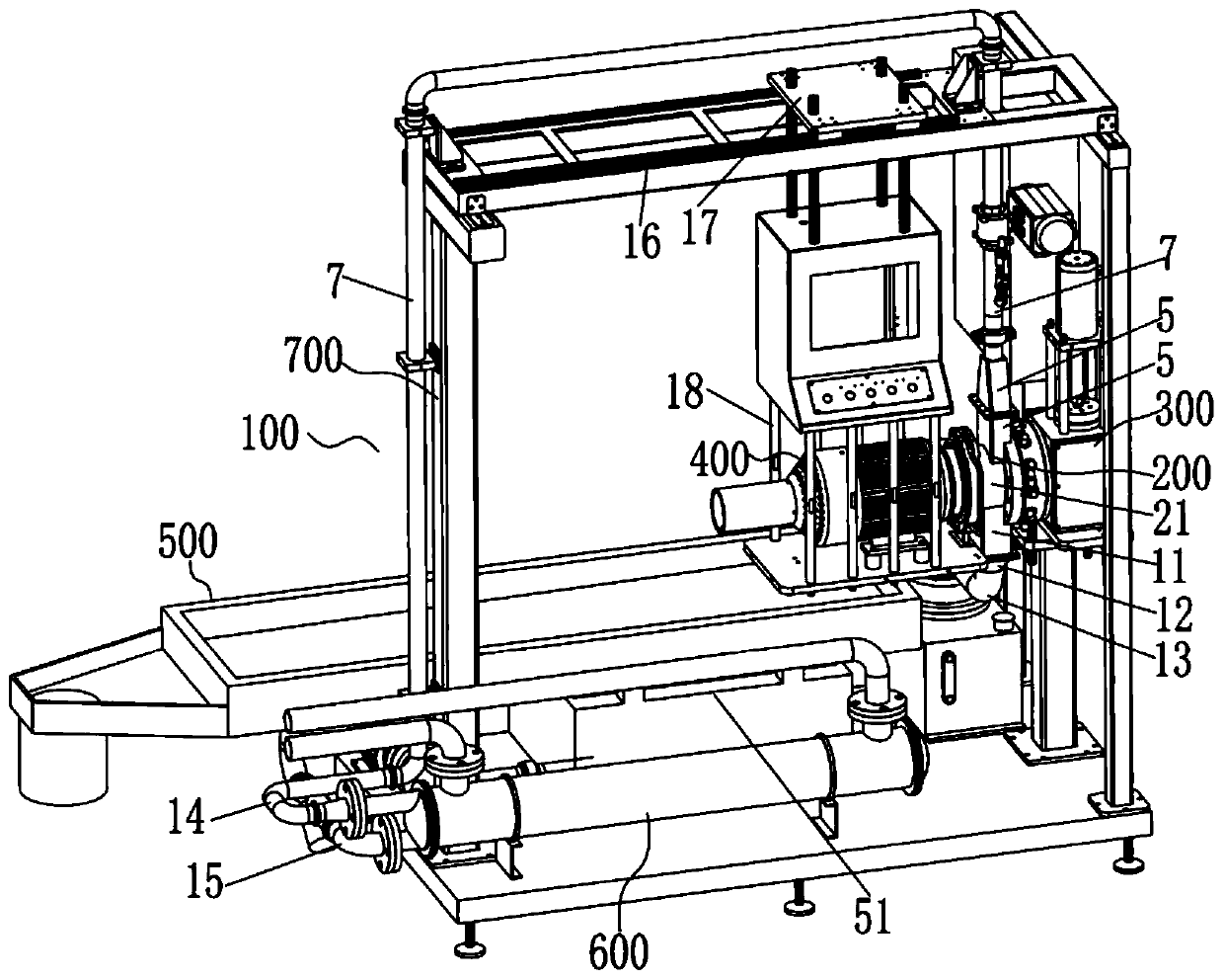
[0005] The technical problem solved by the present invention is to provide an underwater granulator for glass fiber or carbon fiber granulation, aiming at the above-mentioned problems in the prior art, by using a water shower net to spray the injected water into the cutting chamber and Particle mixing can solve the problem of short service life of the cutting chamber, cutting knife and die head of the existing glass fiber or carbon fiber pelletizer, and a lot of cutting hair and debris, and realize less wear and less particle hair of the glass fiber or carbon fiber pelletizer debris

Method used


Image

  • Underwater granulator for granulating glass fibers or carbon fibers
  • Underwater granulator for granulating glass fibers or carbon fibers
  • Underwater granulator for granulating glass fibers or carbon fibers

Examples


Embodiment Construction

[0026] The present invention will be described in further detail below in conjunction with the accompanying drawings.

[0027] The embodiments described by referring to the figures are exemplary and are intended to explain the present application and should not be construed as limiting the present application. In the description of the present application, it should be understood that the terms "center", "longitudinal", "transverse", "length", "width", "thickness", "upper", "lower", "front", " Orientation or position indicated by "back", "left", "right", "vertical", "horizontal", "top", "bottom", "inner", "outer", "clockwise", "counterclockwise", etc. The relationship is based on the orientation or positional relationship shown in the drawings, and is only for the convenience of describing the application and simplifying the description, rather than indicating or implying that the referred device or element must have a specific orientation, be constructed and operated in a spe...


PUM


Abstract

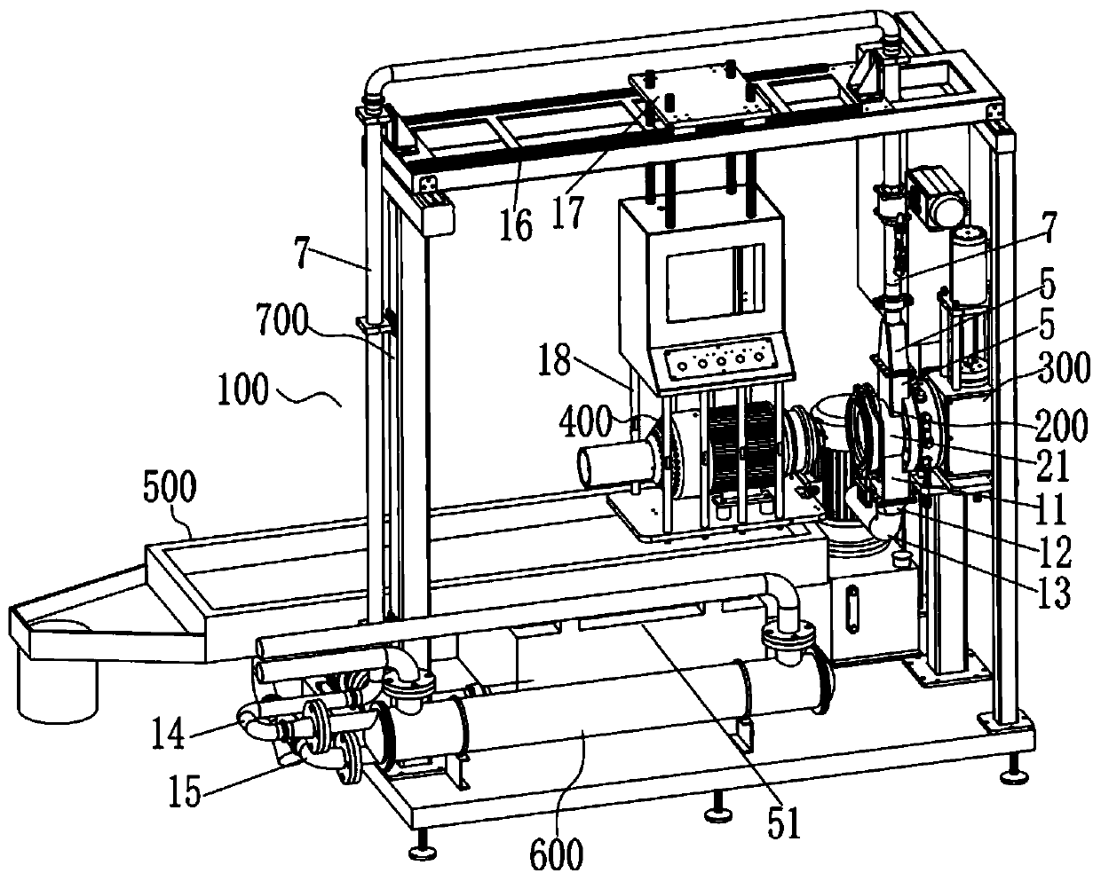
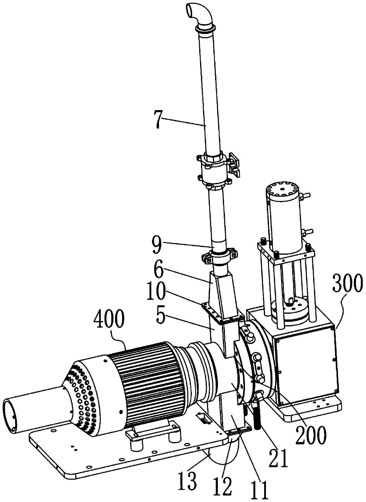
The invention discloses an underwater granulator for granulating glass fibers or carbon fibers. The underwater granulator comprises a cutting chamber, a grinding disc assembly and a cutting knife assembly, wherein the grinding disc assembly and the cutting knife assembly are symmetrically arranged on the two sides of the cutting chamber correspondingly, a cutting knife of the cutting knife assembly and a grinding head of the grinding disc assembly are in butt joint in a rotary cavity of the cutting chamber, a water inlet which is vertically formed and communicates with an inner cavity of the rotary cavity is formed in the rotary cavity, the water inlet is formed in the vertical upper portion of the rotary cavity and is in butt joint with a square material pipe, a first water supply pipe isarranged at the end, relatively away from the water inlet, of the square material pipe, a water supply pipe is in butt joint with the end, relatively away from the square material pipe, of the firstwater supply pipe, a water spraying net is arranged in the square material pipe, the water spraying net can spray supplied water into the rotary cavity, and the sprayed water is directly output alonga discharge hole formed in the vertical lower portion of the rotary cavity after making contact and being mixed with granulated granules in the rotary cavity. According to the underwater granulator, the injected water is sprayed into the cutting chamber through the water spraying net to be mixed with particles, and the problems that a cutting chamber, a cutting knife and a grinding head of an existing glass fiber or carbon fiber granulator are short in service life, and many chips are generated in the granulating process are solved.

Description

technical field [0001] The invention relates to the technical field of plastic pelletizing equipment, in particular to an underwater pelletizer used for pelletizing glass fiber or carbon fiber. Background technique [0002] The underwater granulation and granulation unit generally includes a single-stage or two-stage exhaust extruder, an underwater granulator, a flexible knife seat, an automatic dehydration (drying) device, a vibrating separator, an air delivery system, and a collection hopper. The composition of the control system. When the uniform high-temperature molten material enters the flow channel of the cutting disc from the end of the upstream equipment (reactor / screw extruder / melt pump, etc.), the material is cut into pieces by the high-speed rotating pelletizer blade just after leaving the die hole. The droplet enters the processing water. Due to the physical characteristics of maximizing the specific surface area of ​​the particles and the temperature differenc...

Claims


Application Information

Patent Timeline
Patent Type & Authority Applications(China)
IPC IPC(8): B29B9/06
CPCB29B9/065B01J2/20
Inventor 刘绍兴李花
Owner 广东聚诚智能科技有限公司
Learn More