Bistable flexible machine gripper provided with bionic petal structure and manufacturing method of bistable flexible machine gripper
A bistable, petal technology, applied in the field of robots, can solve the problems of high energy consumption and complex structure, and achieve the effects of low energy consumption, improved grasping ability, and high concealment.
- Summary
- Abstract
- Description
- Claims
- Application Information
AI Technical Summary
Problems solved by technology
Method used
Image
Examples
Embodiment 1
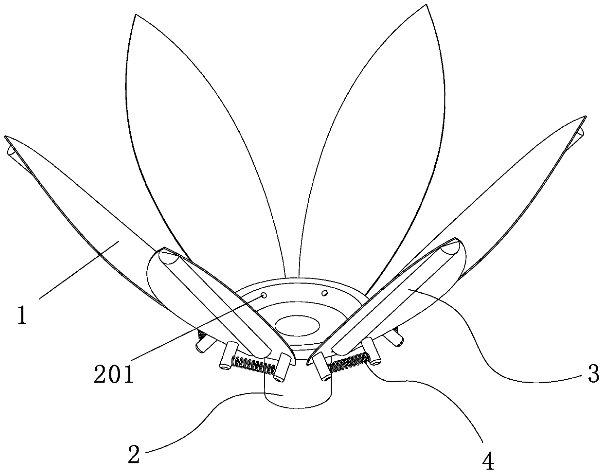
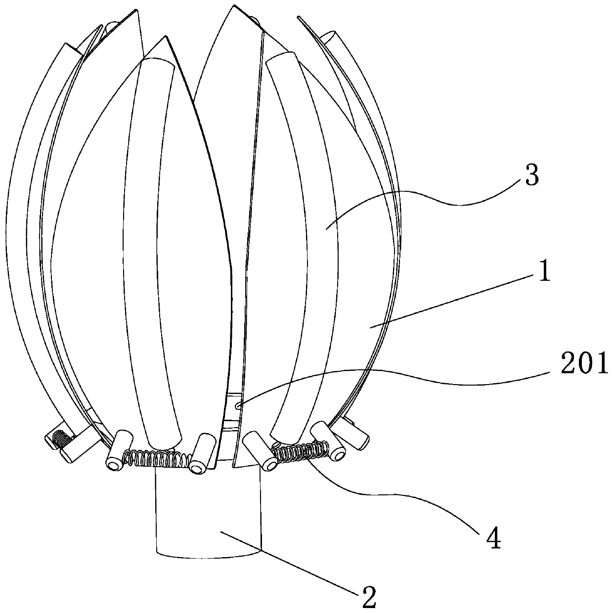
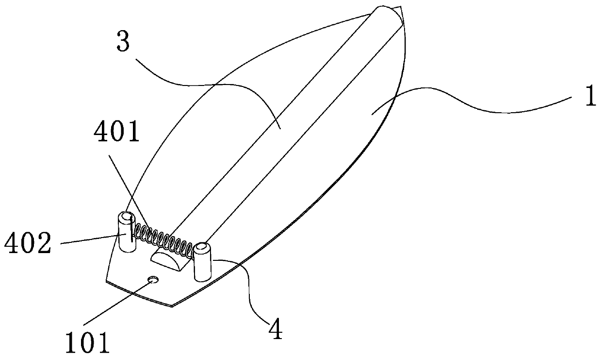
[0047] Such as figure 1 , figure 2 In the shown embodiment 1, a bistable flexible robot gripper with a bionic petal structure includes a base 2, a grasping unit 1 with bistable characteristics, and the grasping unit 1 is set as a bistable structure. The base 2 is made by 3D printing. The base 2 is set in the shape of a truncated cone. The base 2 is provided with a first installation hole 201, and the grasping unit 1 is provided with a second installation hole 101. The base 2 and the grasping The fetching units 1 are fixed by bolt connection, and the grabbing unit 1 is equidistantly fixed around the base 2, and a driving unit is fixed on the grabbing unit 1, and the driving unit includes a The grasping drive unit 3 deformed on one side, the release drive unit 4 used to drive the grasping unit 1 to deform to the side away from the center of the gripper; in order to prevent the items to be grasped from causing damage to the drive unit, the front drive unit is installed on the g...
Embodiment 2
[0050] Such as Figure 5 , Figure 6 As shown, the technical solution of embodiment 2 is basically the same as the technical solution of embodiment 1, the difference is that: the grasping drive unit 3 includes a fluid elastic body 301 which is hollow inside, and is used to limit the radial extension of the fluid elastic body 301 The radial constraint 302, the seal 303 used to seal the fluid elastic body and the air supply line 304 used to drive the deformation of the fluid elastic body, the air cavity 305 is set in the fluid elastic body 301, the air cavity 305 is used to carry the supply The gas filled in the air pipeline 304 forms air pressure to expand and deform the fluid elastic body 301. After the gas supply line 304 fills the air cavity 305 in the fluid elastic body 301 with air pressure, because the fluid elastic body 301 has elasticity, the fluid elastic body 301 It will expand to the surroundings. At this time, the setting of the radial constraint 302 constrains the...
Embodiment 3
[0053] The technical solution of embodiment 3 is basically the same as the technical solution of embodiment 2, and its difference is:
[0054] Such as Figure 7 As shown, the cross section of the air cavity 305 is configured as a fan ring structure, and the air cavity 305 is centrally and symmetrically arranged in the fluid elastic body 301 . In addition, the cross-section of the cylinder can also be set in a circular, semi-circular, etc. shape, but compared with the circular, semi-circular, etc. shape, under the premise of achieving the same result, the air cavity when the cross-section is a fan ring structure The 305 requires minimal air pressure.
PUM
 Abstract
Description
Claims
Application Information
 - R&D
- Intellectual Property
- Life Sciences
- Materials
- Tech Scout
- Unparalleled Data Quality
- Higher Quality Content
- 60% Fewer Hallucinations
Browse by: Latest US Patents, China's latest patents, Technical Efficacy Thesaurus, Application Domain, Technology Topic, Popular Technical Reports.
© 2025 PatSnap. All rights reserved.Legal|Privacy policy|Modern Slavery Act Transparency Statement|Sitemap|About US| Contact US: help@patsnap.com


