Turbine disc and blade locking mechanism for turboprop engine

A locking mechanism, turbine disk technology, applied in the directions of engine components, machines/engines, blade support components, etc., can solve the problems of high difficulty in processing and assembly, complex structure, etc., to improve production efficiency, simple processing difficulty, shortening The effect of processing time

Pending Publication Date: 2020-07-31
上海尚实航空发动机股份有限公司
View PDF0 Cites 4 Cited by
  • Summary
  • Abstract
  • Description
  • Claims
  • Application Information

AI Technical Summary

Problems solved by technology

However, this structure is complex and difficult to process and assemble (see the tenth volume of the aero-engine design manual P227 for illustrations)

Method used


Image

  • Turbine disc and blade locking mechanism for turboprop engine
  • Turbine disc and blade locking mechanism for turboprop engine
  • Turbine disc and blade locking mechanism for turboprop engine

Examples


Embodiment Construction

[0033] In the following, the present invention will be described in detail and specifically through specific examples, so as to better understand the present invention, but the following examples do not limit the scope of the present invention.

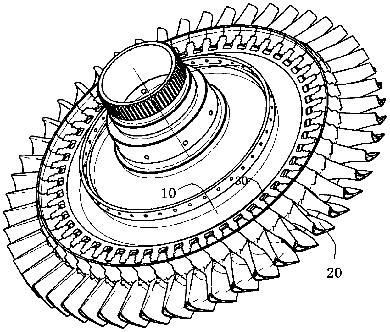
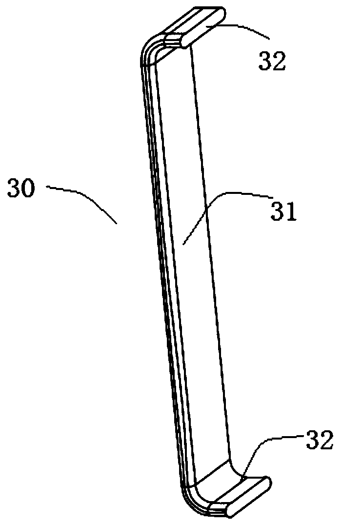
[0034] see figure 1 As shown, this embodiment provides a turbine disk and blade locking mechanism for a turboprop engine, including a turbine disk 10 and a number of blades 20 uniformly distributed around the periphery of the turbine disk 10, and several blades 20 adopt tenon grooves and tenons The connection is embedded on the outer periphery of the turbine disk 10 and locked and fixed by the locking piece 30 . Specifically, the blade 20 uses the tenon structure at its root to embed into the tenon-groove structure of the turbine disk 10 , and the blade 20 is fixed on the turbine disk 10 through the locking piece 30 .

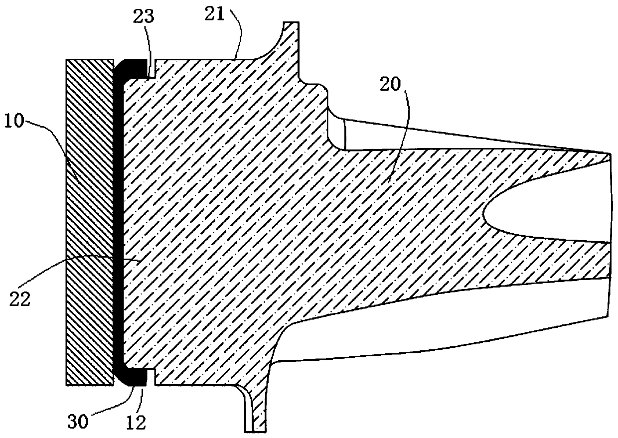
[0035] In this example, see figure 2 As shown, the outer periphery of the turbine disk 10 is evenly distributed w...


PUM


Abstract

The invention discloses a turbine disc and blade locking mechanism for a turboprop engine. The turbine disc and blade locking mechanism comprises a turbine disc and a plurality of blades which are uniformly distributed at the periphery of the turbine disc, wherein mortise structures are uniformly distributed at the periphery of the turbine disc; each mortise structure is composed of a first mortise at the outer side and a second mortise at the inner side, and the first mortise communicates with the second mortise; the root parts of the blades are provided with tenon structures; each tenon structure is composed of a first tenon and a second tenon on the end part of the first tenon; the first tenons are embedded into the first mortises; the second tenons are embedded into the second mortises, and are locked and fixed through blocking plates embedded between the second tenons and the seond mortises. According to the turbine disc and blade locking mechanism for the turboprop engine disclosed by the invention, the blades are matched with the turbine disc though the tenons and the mortises, so that only the locking plates need to insert and bend, and therefore, operations are simple; andmoreover, the turbine disc and blade locking mechanism is novel in design, is simple and convenient in assembly, is high in practicability, is excellent in stable performance, and can be widely applied to turbines of various functions.

Description

technical field [0001] The invention relates to the technical field of turboprop engines, in particular to a turbine disk and blade locking mechanism for a turboprop engine. Background technique [0002] The rotor blades of the turboprop engine work in the harsh environment of high temperature and high speed, and bear the centrifugal force, aerodynamic force, thermal stress and vibration load of the blade itself when the rotor rotates at high speed. Generally, the root of the turbine rotor blade bears high centrifugal force, and the tenon works at high temperature, the mechanical properties of the material will be greatly reduced, and it is very prone to failure. Therefore, in the connection structure of the turbine rotor, the connection between the turbine blade and the turbine disk is very important, and the working environment of the turbine makes the blade bear a huge load. [0003] In the traditional way of fixing the turbine disk and the blade, the turbine blade match...

Claims


Application Information

Patent Timeline
Patent Type & Authority Applications(China)
IPC IPC(8): F01D5/32
CPCF01D5/303F01D5/32
Inventor 戴奎王石柱
Owner 上海尚实航空发动机股份有限公司
Why Eureka
Try Eureka