
Electronic part loading state detection device

A technology of electronic components and loading state, applied in the direction of measuring devices, optical device exploration, instruments, etc., can solve the problems of high price, rising production cost, long analysis time, etc., and achieve the effect of saving cost, improving accuracy and fast analysis time

Active Publication Date: 2020-07-31
TECHWING CO LTD
View PDF20 Cites 0 Cited by
  • Summary
  • Abstract
  • Description
  • Claims
  • Application Information

AI Technical Summary

Problems solved by technology

[0009] In addition, Korean Laid-Open Patent No. 10-2011-0100403 (hereinafter referred to as "Prior Art 2") and the like disclose the technology of using a camera to detect, but in the case of the prior art 2, the surface captured by the camera also needs to be relatively wide
Furthermore, according to the technology disclosed in prior art 2, when the multiple lines constituting the structure of the loading tray are complex, it may be difficult to grasp the loading state of the loading tray in the image captured by the camera, and even if it is grasped, it is necessary to confirm the electronic state. It takes a long time to analyze parts such as Line
In addition, production costs are also increased due to the use of expensive cameras and high-performance analyzers to capture clear images
[0010] Therefore, it is difficult to apply the prior art 1 and the prior art 2 when the electronic components are loaded on the loading tray in a vertical state.

Method used


Image

  • Electronic part loading state detection device
  • Electronic part loading state detection device
  • Electronic part loading state detection device

Examples


Embodiment

[0073] Such as Figure 12 As shown, the detection device 200 (the solid line part) according to this embodiment includes four light irradiators 210a to 210d, four cameras 220a to 220d, an analyzer 230 and two regulators.

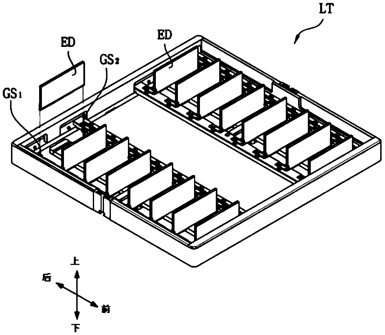
[0074] The four light irradiators 210 a to 210 d are used to irradiate linear laser light to the electronic components ED of the loading tray LT located below. Among them, the loading tray LT as according to figure 1 The embodiment of the present invention is loaded with sixteen electronic components in the form of 8x2 rows and columns and in a vertical state.

[0075] Among the four photoirradiators 210a to 210d, the right two photoirradiators 210a and 210b are used to irradiate laser light to a plurality of electronic components ED in the left column, and the left two photoirradiators 210c and 210d are used to irradiate laser light to the right column. Multiple electronic components ED are irradiated with laser light. In this way, the photoirradiators 2...


PUM


Abstract

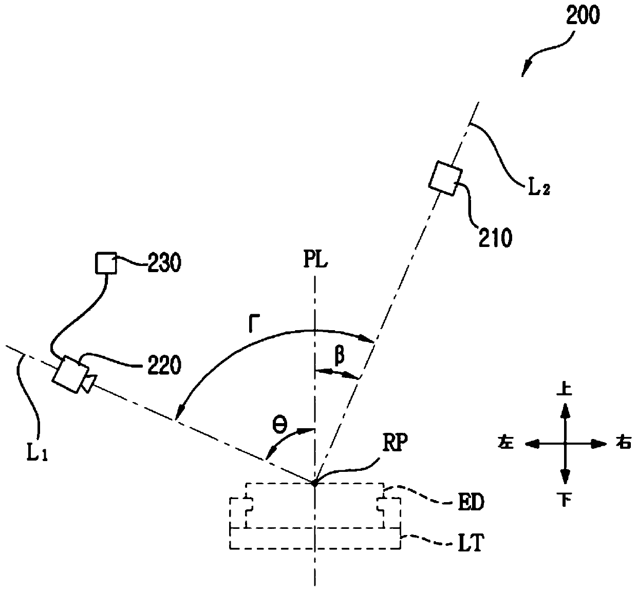
The invention relates to an electronic part loading state detection device comprising at least one light irradiation device, at least one camera, and an analyzer. The light irradiation device is usedto irradiate light on a plurality of electronic parts disposed on loading trays on detection positions. The at least one camera is used to shoot the plurality of electronic parts used to irradiate light by using the light irradiation device. The analyzer is used to analyze the loading states of the electronic parts by the shape of the light in the images acquired by the camera. By viewing from a front side, an included angle between a first line used for connecting a reflection point and the camera and a second line used for connecting the reflection and the light irradiation device is greaterthan 0degree, and is smaller than 180degrees. The above mention reflection point can be one of the connection positions between the light irradiated by the light irradiation device on the electronicparts and the plurality of electronic parts. The changing shapes of the irradiated light are used to detect the loading states of the electronic parts, and a processing speed is fast, and the loadingstates of the electronic parts are determined accurately.

Description

[0001] This application is a divisional application of an invention application with an application date of December 21, 2016, an application number of 201611192151.7, and an invention title of "electronic component loading state detection device". technical field [0002] The present invention relates to an electronic component loading state detection device for detecting whether electronic components are properly loaded on a loading tray on which electronic components can be loaded. Background technique [0003] Electronic components such as solid-state drives (SSD, Solid-state Drive) or memory sticks need to go through label attachment operations, casing operations, and electrical characteristic testing operations before leaving the factory. [0004] In order to perform the above work, electronic components often need to be transported in a state loaded on a loading tray. Of course, usually multiple electronic components are loaded together on the loading tray. [0005] ...

Claims


Application Information

Patent Timeline
Patent Type & Authority Applications(China)
IPC IPC(8): G01V8/10G01D21/02
CPCG01D21/02G01V8/10G01V8/22G01N21/39G01N2015/1438
Inventor 卢种基李斗吉
Owner TECHWING CO LTD
Learn More