Waveguide display device and augmented reality display equipment

A display device and waveguide technology, applied in optical components, optics, instruments, etc., can solve the problems of prone to chromatic aberration, complex and difficult processes, and low manufacturing costs.

Pending Publication Date: 2020-07-31
谷东科技有限公司
View PDF7 Cites 2 Cited by
  • Summary
  • Abstract
  • Description
  • Claims
  • Application Information

AI Technical Summary

Problems solved by technology

[0003] Nowadays, the main waveguide technologies are divided into two categories: geometric waveguides and diffractive waveguides. Geometric waveguides have better imaging quality and are not prone to chromatic aberration, but the manufacturing cost is high and the process is complicated and difficult; diffractive waveguides are prone to imaging after several diffractions. Chromatic difference, but the manufacturing cost is low and the process is simple, both methods have their own advantages and disadvantages

Method used


Image

  • Waveguide display device and augmented reality display equipment
  • Waveguide display device and augmented reality display equipment
  • Waveguide display device and augmented reality display equipment

Examples


Embodiment Construction

[0033] Reference will now be made in detail to the exemplary embodiments, examples of which are illustrated in the accompanying drawings. When the following description refers to the accompanying drawings, the same numerals in different drawings refer to the same or similar elements unless otherwise indicated. The implementations described in the following exemplary examples do not represent all implementations consistent with the present disclosure. Rather, they are merely examples of apparatuses and methods consistent with aspects of the present disclosure as recited in the appended claims.

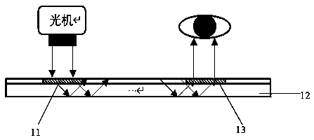
[0034] figure 1 A schematic diagram of the principle of a diffractive optical waveguide is shown. Such as figure 1 As shown, diffraction gratings are used in both the light wave input region and the light wave output region of the waveguide substrate. When the light from the optical machine hits the first diffraction grating 11 in the light wave input region, another beam of light wi...


PUM


Abstract

The invention relates to a waveguide display device and augmented reality display equipment. The waveguide display device comprises a waveguide substrate, a geometrical optical input element and a diffractive optical output element, wherein the geometrical optical input element is arranged in the light wave input area of the waveguide substrate and is used for coupling input light waves into the waveguide substrate in a geometrical optical mode; the waveguide substrate is used for transmitting the light waves coupled into the waveguide substrate through the geometrical optical input element tothe diffractive optical output element in a total reflection mode; the diffractive optical output element is arranged in the light wave output area of the waveguide substrate and used for outputtinglight waves transmitted to the diffractive optical output element in a diffractive optical mode.

Description

technical field [0001] The present disclosure relates to the technical field of augmented reality display, in particular to a waveguide display device and augmented reality display device. Background technique [0002] With the development of virtual reality and augmented reality technology, near-eye display devices have developed rapidly. The near-eye display of augmented reality is a technology that images light fields in real space, and can take into account both virtual and real operations. Coupling image light into the human eye using traditional optical waveguide components has been used, including the use of prisms, mirrors, transflective waveguides, holograms, and diffraction gratings. The optical waveguide display system uses the principle of total reflection to realize light wave transmission, combined with diffraction elements to realize directional transmission of light, and then guides the image light to the human eye, so that users can see the projected image. ...

Claims


Application Information

Patent Timeline
IPC IPC(8): G02B27/01
CPCG02B27/0172G02B2027/0174
Inventor 崔海涛
Owner 谷东科技有限公司
Why Eureka
Try Eureka