
Experimental device for researching flow drift under non-uniform heat flow boundary

An experimental device and lower flow technology, applied in the field of experimental devices for studying flow drift, can solve problems such as flow instability, system hazards, inability to meet non-uniform heat flow boundary conditions, etc., and achieve the effect of improving flow drift

Inactive Publication Date: 2020-07-31
TIANJIN UNIV
View PDF6 Cites 0 Cited by
  • Summary
  • Abstract
  • Description
  • Claims
  • Application Information

AI Technical Summary

Problems solved by technology

The existing experimental devices cannot meet the boundary conditions of various non-uniform heat flow in reality, and there is a lack of settings for the boundary conditions of non-uniform heat flow
The Chinese invention patent application with the publication number CN103219055B "A device for detecting the instability of interstitial flow in a nuclear reactor" adopts a rising section of simulated flow instability, which is equivalent to a 90-degree inclination angle of the device, and lacks the ability to prevent the flow instability of the device at various inclination angles. Stable experimental investigation, unable to conduct controlled experiments, resulting in methods to improve flow instability
[0004] In summary, flow instability, especially flow drift, in a gas-liquid phase change system will cause great harm to the system. Exploring the characteristics of flow drift and finding ways to improve flow drift are problems that need to be solved urgently.

Method used


Image

  • Experimental device for researching flow drift under non-uniform heat flow boundary
  • Experimental device for researching flow drift under non-uniform heat flow boundary
  • Experimental device for researching flow drift under non-uniform heat flow boundary

Examples


Embodiment Construction

[0024] The present invention will be described in further detail below through specific examples. The following examples can enable those skilled in the art to understand the present invention more comprehensively, but do not limit the present invention in any way.

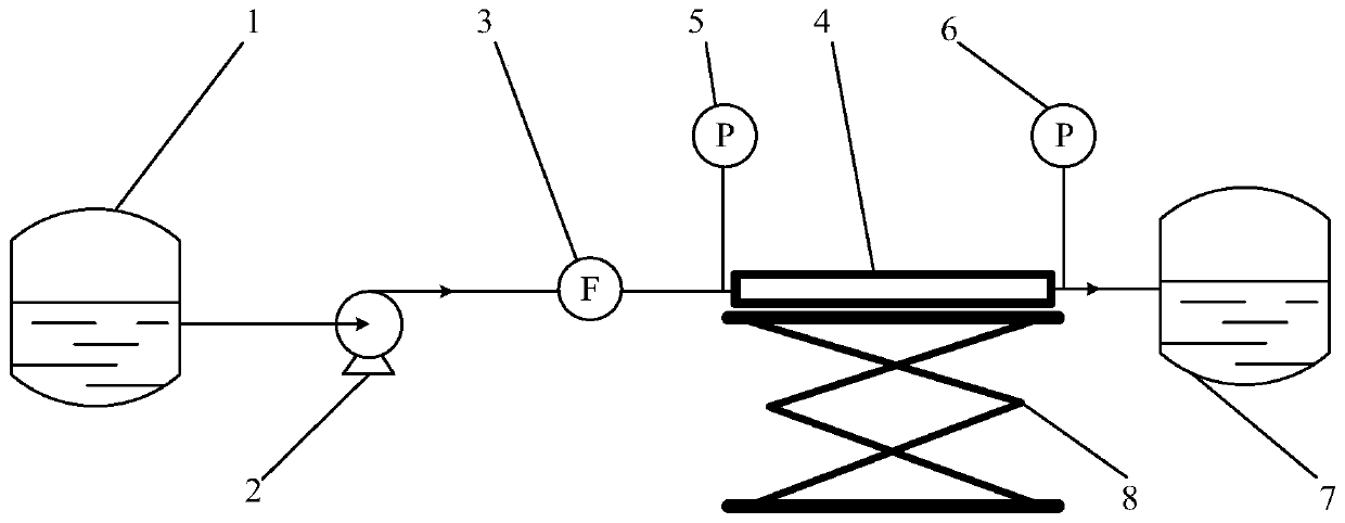
[0025] Such as figure 1 As shown, this embodiment discloses an experimental device for studying flow drift under a non-uniform heat flow boundary, including a first liquid storage tank 1, a working fluid pump 2, a flow meter 3, an experimental body group 4, and a first pressure sensor 5. The second pressure sensor 6, the second liquid storage tank 7, and the lifting platform 8.

[0026] The outlet of the first liquid storage tank 1 is connected to the inlet of the working fluid pump 2, the outlet of the working fluid pump 2 is connected to the inlet of the flowmeter 3, the outlet of the flowmeter 3 is connected to the inlet of the experimental body group 4, and the outlet of the experimental body group 4 is connec...


PUM


Abstract

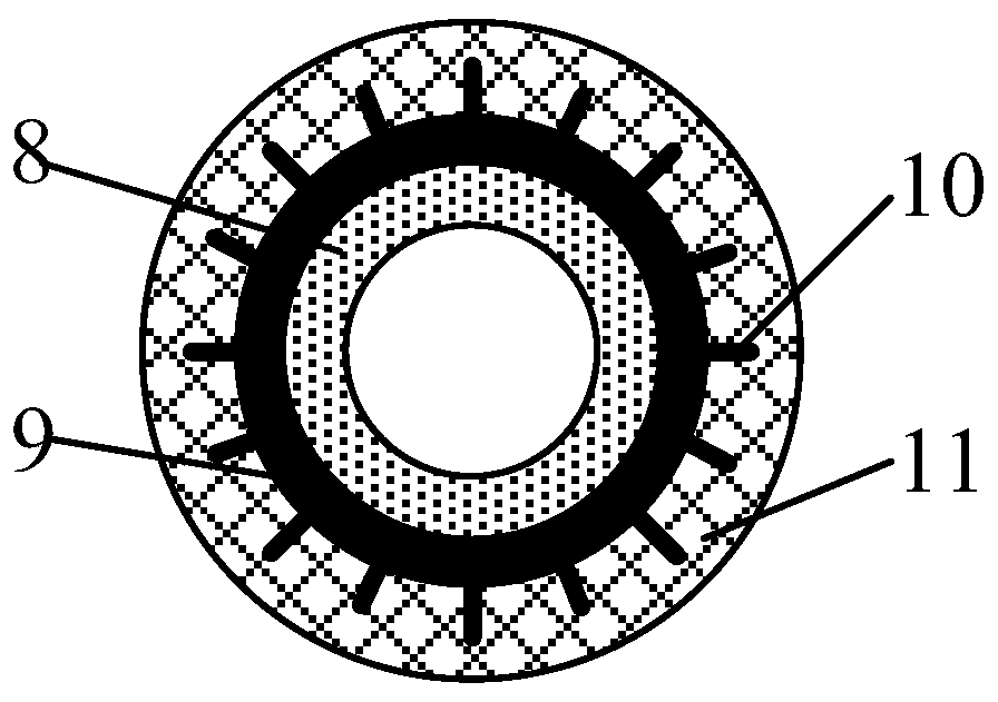
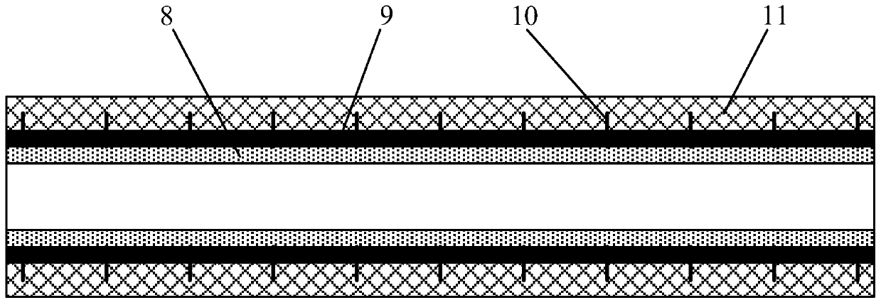
The invention belongs to the field of hydrodynamic experiments, and discloses an experimental device for researching flow drift under a non-uniform heat flow boundary. An outlet of a first liquid storage tank is connected with an inlet of an experimental body group sequentially through a working medium pump and a flow meter, and an outlet of the experimental body group is connected with a second liquid storage tank; a first pressure sensor is arranged at an inlet of the experimental body group, and a second pressure sensor is arranged at an outlet; the experimental body group comprises a steelpipe, a plurality of heating sheets uniformly cover the outer part of the steel pipe in the circumferential direction, and the heating power of each heating sheet can be respectively controlled, so that circumferential uniform heat flow or circumferential non-uniform heat flow is provided for the steel pipe; thermocouples used for measuring temperature are arranged outside the steel pipe, and thethermocouples are evenly arranged in the circumferential direction and the axial direction of the steel pipe respectively. Non-uniform heat flow boundary conditions can be realized, experimental research on flow drift in a gas-liquid phase change system is carried out, and a method for improving flow drift is explored.

Description

technical field [0001] The invention belongs to the field of fluid dynamics experiments, and more specifically relates to an experimental device for studying flow drift. Background technique [0002] Flow instability often occurs in the boiling process of two-phase flow. Flow instability can be divided into static instability and dynamic instability, among which flow drift is a relatively common phenomenon of static instability. Flow drift is caused by the negative slope region of the pipeline pressure drop-mass flux curve. When the fluid is at a certain point in the negative slope area, if the flow is disturbed, the fluid will deviate from the original working condition and run in a new working condition. If the flow rate decreases due to flow drift, it will cause the pipeline to burn out, which will cause great harm to the boiling channel; if the flow rate drift causes the flow rate to increase, it will cause the dryness of the equipment outlet to be too low, which will a...

Claims


Application Information

Patent Timeline
Patent Type & Authority Applications(China)
IPC IPC(8): G09B23/12
CPCG09B23/12
Inventor 赵力卢雅妮赵东鹏邓帅陈丽锦
Owner TIANJIN UNIV
Learn More