
Laser line front sight alignment experiment device for machining and method thereof

A technology of mechanical processing and experimental equipment, which is applied in the direction of laser welding equipment, metal processing equipment, manufacturing tools, etc., can solve the problems of troublesome laser line alignment experiment process, inability to guarantee the accuracy of laser processing, and inability to guarantee the adjustment accuracy, etc., to achieve Effects of improved adjustability, increased speed, and improved processing quality

Inactive Publication Date: 2022-03-08
WENZHOU UNIVERSITY
View PDF0 Cites 0 Cited by
  • Summary
  • Abstract
  • Description
  • Claims
  • Application Information

AI Technical Summary

Problems solved by technology

[0003] 1. The existing laser line alignment experiment cannot be adjusted according to the needs, resulting in poor calibration efficiency and the accuracy of laser processing cannot be guaranteed;
[0004] 2. Secondly, the existing laser line alignment experiment process is cumbersome, and the adjustment accuracy cannot be guaranteed, and its experimental rotation cannot be adjusted frequently

Method used


Image

  • Laser line front sight alignment experiment device for machining and method thereof
  • Laser line front sight alignment experiment device for machining and method thereof
  • Laser line front sight alignment experiment device for machining and method thereof

Examples


Embodiment Construction

[0033] The following will clearly and completely describe the technical solutions in the embodiments of the present invention with reference to the accompanying drawings in the embodiments of the present invention. Obviously, the described embodiments are only some, not all, embodiments of the present invention. Based on the embodiments of the present invention, all other embodiments obtained by persons of ordinary skill in the art without making creative efforts belong to the protection scope of the present invention.

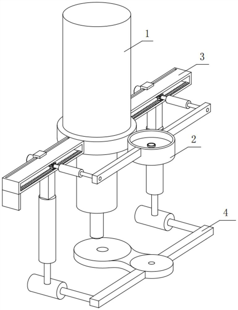
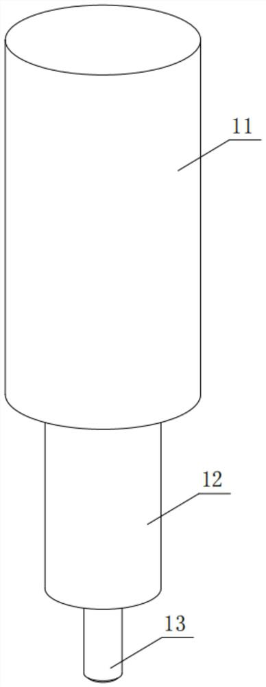
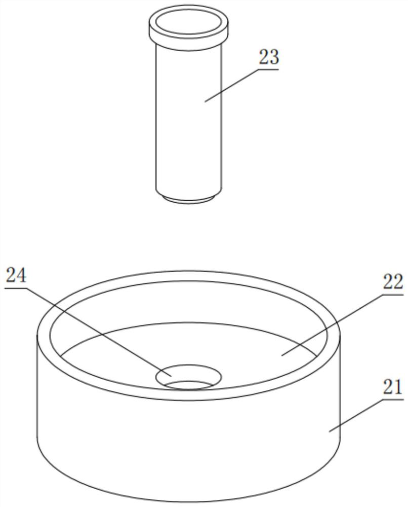
[0034] see figure 1 , an experimental device for aligning laser line sights for mechanical processing, including a laser processing part 1, a calibration device 2 is provided at the side end of the laser processing part 1, and the two ends of the calibration device 2 are sleeved on the laser processing part 1 through an adjustment device 3 , the alignment experiment component 4 is arranged under the laser processing part 1 , and the alignment experiment componen...


PUM


Abstract

The invention discloses a laser line front sight alignment experiment device for machining and a method thereof, belongs to the technical field of laser line alignment, and aims to solve the problems that the existing laser line alignment experiment cannot be adjusted as required, so that the calibration efficiency is poor, and the accuracy of laser machining cannot be ensured. Secondly, the existing laser line alignment experiment process is troublesome, the adjustment precision cannot be guaranteed, and the position cannot be adjusted frequently in the experiment process. The transverse telescopic air cylinder is used for adjusting the left-right position of the calibration laser lamp and used for being aligned with the calibration plate, through the arrangement of the power assembly, the position of the calibration device is effectively adjusted, the overall adjustability of the calibration device is improved, the adjustment flexibility is improved, the calibration experiment speed is increased, and accurate positioning is guaranteed; the positioning precision is greatly improved, the adjustment precision is guaranteed, the laser line front sight alignment efficiency is improved, calibration positioning is effectively carried out, experiment conditions are met, the overall structure is simple, adjustment is convenient, and the calibration precision is high.

Description

technical field [0001] The invention relates to the technical field of laser line alignment, in particular to an experimental device and method for aligning laser line sights for mechanical processing. Background technique [0002] Laser processing technology is a processing technology that uses the characteristics of the interaction between laser beams and substances to perform cutting, welding, surface treatment, drilling and micro-processing of materials (including metals and non-metals). As an advanced manufacturing technology, laser processing has been widely used in important sectors of the national economy such as automobiles, electronics, electrical appliances, aviation, metallurgy, and machinery manufacturing. It has played an increasingly important role in improving product quality, labor productivity, automation, pollution-free, and reducing material consumption. It plays an important role. Before laser processing, it is necessary to conduct an alignment experimen...

Claims


Application Information

Patent Timeline
Patent Type & Authority Applications(China)
IPC IPC(8): B23K26/70
CPCB23K26/705
Inventor 潘晓铭夏琨叶月霞舒晨晨姚广林潘敏辉
Owner WENZHOU UNIVERSITY
Learn More