Integrated micro-jet vapor chamber radiator and manufacturing method thereof
A vapor chamber and heat sink technology, which is applied in the direction of electric solid state devices, semiconductor devices, semiconductor/solid state device components, etc., to achieve the effect of improving heat dissipation performance, improving heat dissipation capacity, and eliminating contact thermal resistance.
- Summary
- Abstract
- Description
- Claims
- Application Information
AI Technical Summary
Problems solved by technology
Method used
Image

Examples
Embodiment 1
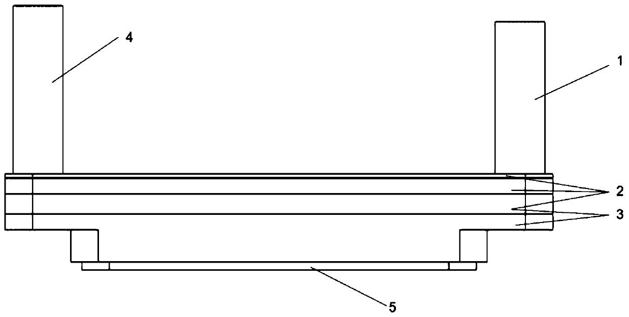
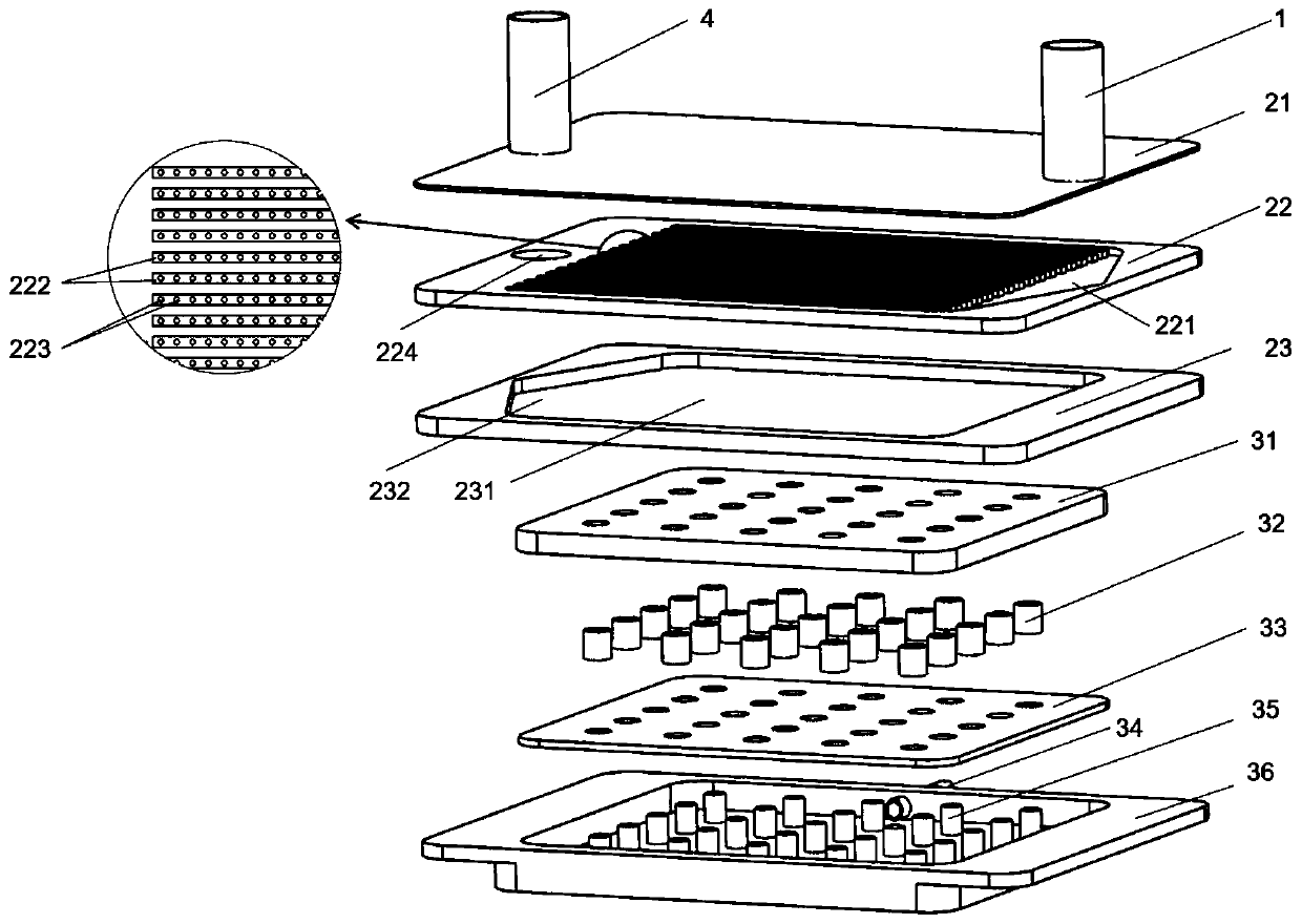
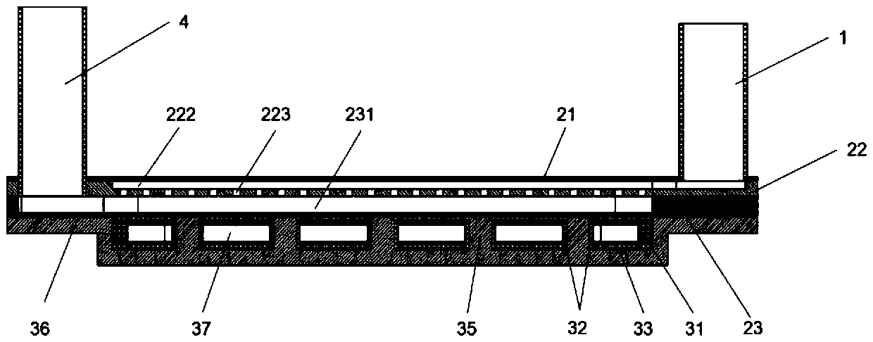
[0046] Such as figure 1 , figure 2 and image 3 As shown, an integrated micro-spray vapor chamber radiator includes an inlet pipe 1, a micro-spray assembly 2, a vapor chamber body assembly 3 and an outlet pipe 4, and the vapor chamber body assembly is installed on the surface of a heating chip 5 , the inlet pipe and the outlet pipe are parallel and located on the same side or different sides of the integrated micro-spray vapor chamber radiator.
[0047] The micro-injection assembly is arranged above the vapor chamber body assembly, and the micro-injection assembly includes a cover plate 21, an injection plate 22, and a condensation plate 23 from top to bottom, and the cover plate, injection plate, and condensation plate are stacked. .
[0048] The cover plate is provided with a cooling medium inlet and a cooling medium outlet, the cooling medium inlet communicates with the inlet pipeline, and the cooling medium outlet communicates with the outlet pipeline.
[0049] At lea...
Embodiment 2
[0070] Such as Figure 4 , Figure 5 and Figure 6 As shown, the difference between this embodiment and Embodiment 1 is that a cone-hole spray plate 24 is set between the spray plate and the condensation plate, that is, the micro-injection assembly includes a cover plate, a spray plate, and a cone-hole spray plate in this embodiment. and cold plate.
[0071] Described conical hole spraying plate 24 is provided with spraying micro-cone hole array 241 and cooling medium outlet; The center position and the hole number of the hole of spraying micro-cone hole array 241 and the center position and the hole number of spraying micro-hole array 223 on spraying plate 22 The number of holes is consistent, and its purpose is to increase the injection area of the array jets passing through the injection plate 22 and improve the heat dissipation efficiency of the radiator; The manifold 232 on the top communicates with the conical hole injection plate 24 , the cooling medium outlet 224 ...
Embodiment 3
[0075] Such as Figure 4 , Figure 7 and Figure 8 As shown, the difference between this embodiment and Embodiment 1 is that a cooling medium inlet 225 is added to the injection plate 22 of Embodiment 1, and a second injection plate 25 is added between the injection plate 22 and the condensation plate 23. The structure of the second injection plate is roughly the same as that of the injection plate, and it is provided with a split cavity, a parallel micro-groove flow channel, an array of injection microholes, and a cooling medium outlet. The position of the micro-groove flow channel 251 is consistent with and aligned with the positions of the split chamber and the parallel micro-groove flow channel in the injection plate 22, and the number of holes of the injection micro-hole array 252 of the second injection plate is smaller than that of the injection micro-hole array of the injection plate. Number is many, and its purpose is to increase the density that forms array jet and...
PUM
 Abstract
Description
Claims
Application Information
 - R&D
- Intellectual Property
- Life Sciences
- Materials
- Tech Scout
- Unparalleled Data Quality
- Higher Quality Content
- 60% Fewer Hallucinations
Browse by: Latest US Patents, China's latest patents, Technical Efficacy Thesaurus, Application Domain, Technology Topic, Popular Technical Reports.
© 2025 PatSnap. All rights reserved.Legal|Privacy policy|Modern Slavery Act Transparency Statement|Sitemap|About US| Contact US: help@patsnap.com