
Radio frequency power amplifier

A technology of radio frequency power and amplifier, applied in the field of radio frequency power amplifier, can solve the problems of limited second harmonic suppression, difficulty in meeting requirements of second harmonic, and higher output power level, so as to achieve the effect of saving components and improving the suppression capability.

Pending Publication Date: 2020-07-31
IPGOAL MICROELECTRONICS (SICHUAN) CO LTD
View PDF0 Cites 0 Cited by
  • Summary
  • Abstract
  • Description
  • Claims
  • Application Information

AI Technical Summary

Problems solved by technology

[0004] In the above RF power amplifier circuit, the resonant network that suppresses the second harmonic for the first time simply realizes the reduction of the impedance modulus through the equivalent parallel connection, which makes the The number of resonant networks is really large; in addition, the second resonant network that suppresses the second harmonic is just a simple combination of parallel resonant network and series network. Since the load impedance connected to the RF power amplifier is relatively large (50 ohms), The suppression of the second harmonic is relatively limited; thus, when the output power level of the above-mentioned RF power amplifier increases, the suppression of the second harmonic is difficult to meet the requirements in actual use, and the suppression of the second harmonic is realized The circuit used is complex and has many components, which is not conducive to cost control

Method used


Image

  • Radio frequency power amplifier
  • Radio frequency power amplifier
  • Radio frequency power amplifier

Examples


Embodiment Construction

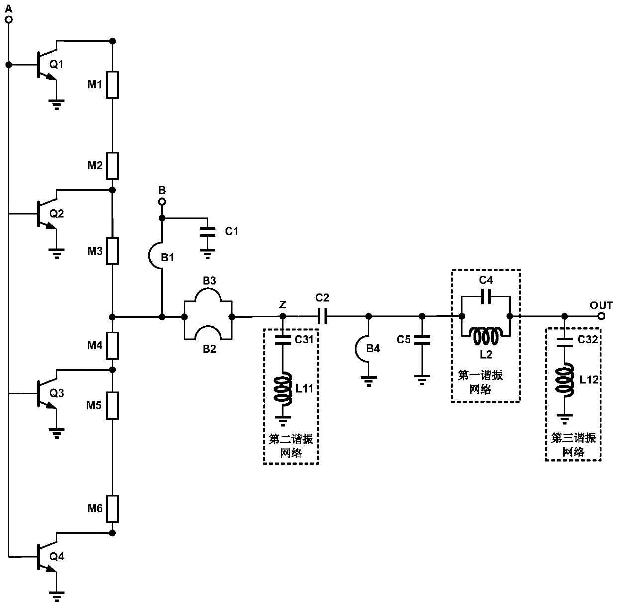
[0018] Embodiments of the present invention will now be described with reference to the drawings, in which like reference numerals represent like elements. As mentioned above, the present invention provides a radio frequency power amplifier. The radio frequency power amplifier of the present invention not only reduces the complexity of the circuit, but also improves the capability of suppressing the second harmonic of the radio frequency power amplifier.

[0019] Please refer to figure 2 , figure 2 It is a structural schematic diagram of the radio frequency power amplifier of the present invention. As shown in the figure, the radio frequency power amplifier of the present invention includes a power tube unit and a harmonic suppression unit, and the power tube unit includes several triodes and several microstrip lines; the harmonic suppression unit is connected to the middle position of the power tube unit . Wherein, the power tube unit specifically includes four triodes Q...


PUM


Abstract

The invention discloses a radio frequency power amplifier which comprises a power tube unit and a harmonic suppression unit. The harmonic suppression unit is connected to the middle position of the power tube unit. The harmonic suppression unit comprises a first bonding wire, a second bonding wire, a third bonding wire, a fourth bonding wire, a first capacitor, a second capacitor and a first resonance network. The power tube unit further comprises a second resonance network and a third resonance network, one end of the second resonance network is connected with one end of the second capacitor,the other end of the second resonance network is grounded, one end of the third resonance network is connected with the output terminal, the other end of the third resonance network is grounded, andno resonance network is connected in the power tube unit. According to the radio frequency power amplifier disclosed by the invention, the complexity of the circuit is reduced, and the capability of suppressing the second harmonic of the radio frequency power amplifier is improved.

Description

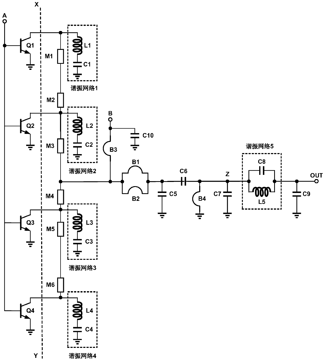
technical field [0001] The present invention relates to the field of radio frequency microwaves, and more particularly relates to a radio frequency power amplifier. Background technique [0002] The circuit structure of the existing commonly used RF power amplifier is as follows: figure 1 As shown, where the output matching circuit of the RF power amplifier is figure 1 The circuit on the right side of the dotted line XY. exist figure 1 In the circuit structure diagram of the RF amplifier shown, OUT is the signal output terminal of the power amplifier, which is generally connected to a load with an impedance of 50 ohms; Q1, Q2, Q3, and Q4 are RF power tubes (transistors) of the same type and size ; M1, M2, M3, M4, M5, M6 microstrip lines of the same size are used to connect the collectors (or drains) of the RF power transistors Q1, Q2, Q3, and Q4; the inductor L1 and the capacitor C1 form a resonant network 1. Inductor L2 and capacitor C2 form a resonant network 2. Induct...

Claims


Application Information

Patent Timeline
Patent Type & Authority Applications(China)
IPC IPC(8): H03F3/189H03F3/20
CPCH03F3/189H03F3/20
Inventor 刘元鑫张宗楠吴杰刘辉
Owner IPGOAL MICROELECTRONICS (SICHUAN) CO LTD
Learn More