
Gas-liquid separator for separating at least one liquid component from gaseous component

A gas-liquid separator, liquid technology, applied in separation methods, semi-permeable membrane separation, dispersed particle separation, etc., can solve problems such as component separation, and achieve the effect of improving efficiency, saving costs, and reducing demand

Pending Publication Date: 2020-07-31
ROBERT BOSCH GMBH
View PDF12 Cites 0 Cited by
  • Summary
  • Abstract
  • Description
  • Claims
  • Application Information

AI Technical Summary

Problems solved by technology

Thus, gas-liquid separators have the disadvantage that not only approximately pure hydrogen, but also additional heavy components, such as N 2 is also fed back into the fuel cell
However, such outlet valves have the following disadvantages on the one hand: 2 H 2 component separation

Method used


Image

  • Gas-liquid separator for separating at least one liquid component from gaseous component
  • Gas-liquid separator for separating at least one liquid component from gaseous component
  • Gas-liquid separator for separating at least one liquid component from gaseous component

Examples


Embodiment Construction

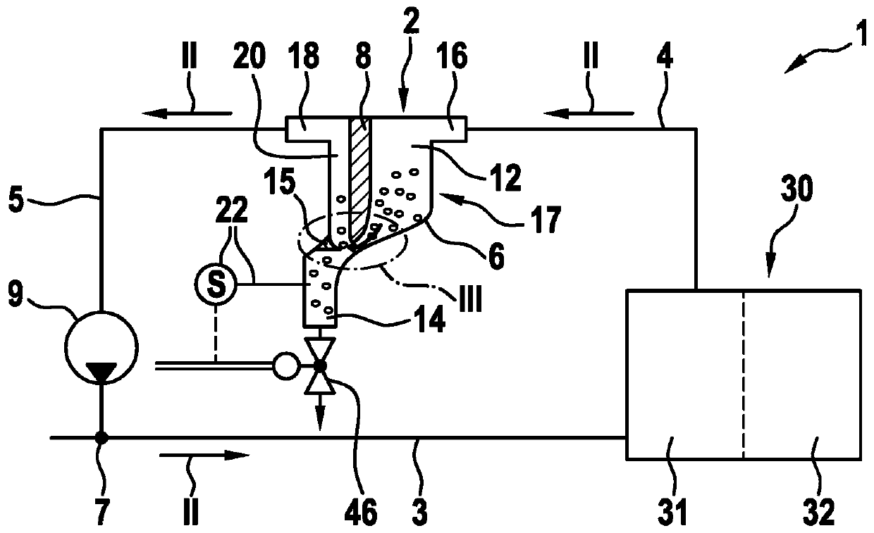
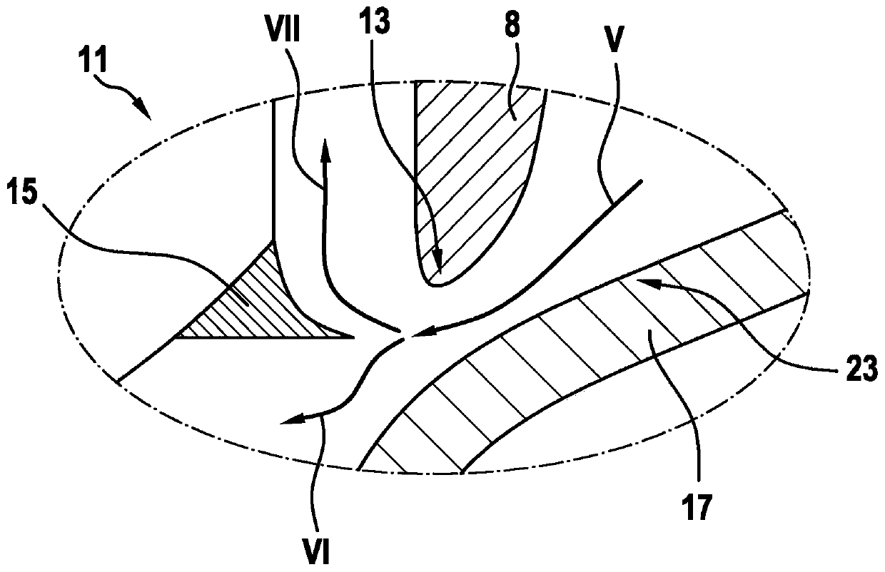
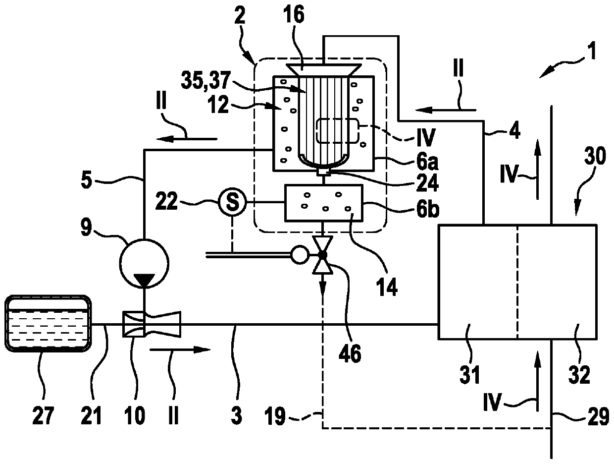
[0022] according to figure 1 and figure 2 The diagram of shows a fuel cell system 1 with a first embodiment of a gas-liquid separator 2 according to the invention, wherein the gas-liquid separator 2 removes liquid components, especially H 2 O addition to the gaseous component N 2 Separate from medium. Here, component H 2 O and N 2 By means of the centrifugal principle and the medium, especially the component H of the medium 2 The separation is carried out by means of the gas-liquid separator 2 according to the invention.

[0023] exist figure 1 shows a fuel cell system 1 in which a fuel cell 30 , a gas-liquid separator 2 and an optional recirculation pump 9 are fluidically connected to one another by means of lines. The fuel cell 30 has an anode region 31 and a cathode region 32 and is used, in particular in vehicles, to 2 and oxygen, ie O 2 reaction to generate energy. Here, energy can be generated in the form of electrical energy. In this case, the gas-liquid sep...


PUM


Abstract

The invention relates to a gas-liquid separator (2) for separating at least one liquid component, in particular H2O, from a gaseous component, in particular H2, the separator comprising at least one container (6) which is supplied with a medium via an inlet (16), at least the liquid component of the medium being separated in at least one container (6) and the separated component of the medium being discharged from the at least one container (6) via a discharge valve (46) with the remaining gaseous component of the medium, in particular H2, being recirculated into an outflow line (5) via a first outlet (18). According to the invention, in addition to the liquid component, in particular H2O, a gaseous component N2 is separated from the medium by the gas-liquid separator (2).

Description

technical field [0001] The invention relates to a gas-liquid separator for separating at least one liquid component from a gaseous component, to which a medium is supplied via an inlet, wherein the separation of at least one liquid component of the medium takes place in at least one container Isolation, in particular for use in fuel cell systems of vehicles with a fuel cell drive. Background technique [0002] Gaseous fuels will also play an increasingly important role in the vehicle sector in the future in addition to liquid fuels. Especially in vehicles with a fuel cell drive, the hydrogen gas flow must be controlled. Here, the gas flow is no longer discontinuously controlled as in the case of liquid fuel injection, but the gas is taken from at least one high-pressure tank and directed via the inflow line of the medium-pressure line system to the injector unit. The injector unit conducts the gas to the fuel cell via the connecting lines of the low-pressure piping system....

Claims


Application Information

Patent Timeline
IPC IPC(8): F16T1/12H01M8/04119
CPCF16T1/12H01M8/04164H01M8/04097B01D45/06B01D63/06B01D53/24B01D2053/223Y02E60/50B01D45/16B01D53/22F16T1/00H01M2250/20B01D63/069
Inventor M·库尔茨
Owner ROBERT BOSCH GMBH
Learn More