
Profile cutting method for laser cutting automatic production line

An automatic production line and cutting method technology, applied in the direction of laser welding equipment, welding/cutting auxiliary equipment, auxiliary devices, etc., can solve the problems of low blanking efficiency, affecting profile processing and production, and achieve high blanking efficiency, convenient processing, The effect of easy distribution

Active Publication Date: 2020-08-04
FOSHAN HONGSHI LASER TECH CO LTD
View PDF9 Cites 10 Cited by
  • Summary
  • Abstract
  • Description
  • Claims
  • Application Information

AI Technical Summary

Problems solved by technology

[0008] This patent application can process the entire profile, and cooperate with the special blanking area to form wedges, bolts and various holes on the entire profile. However, in various machinery manufacturing and processing industries such as machinery and ships, Sometimes it is necessary to process workpieces with different profile lengths, for example, to form long materials (length greater than or equal to 1 meter) and short materials (length less than 1 meter), and the blanking area of ​​this patent application is uniform blanking, which requires further sorting , increasing the sorting process will lead to low cutting efficiency, which will eventually affect the processing and production of profiles

Method used


Image

  • Profile cutting method for laser cutting automatic production line
  • Profile cutting method for laser cutting automatic production line
  • Profile cutting method for laser cutting automatic production line

Examples


Embodiment 1

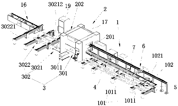
[0061] refer to figure 1 , this embodiment discloses a laser cutting automatic production line, including a feeding area 1, a cutting area 2 and a feeding area 3, a storage rack 101 and a feeding table 102 are arranged in the loading area 1, and the storage rack 101 is used for For storing the profile 4 to be processed, the profile 4 can be hoisted by a crane to the storage rack 101 for temporary storage;

[0062] refer to figure 1 , the storage rack 101 is also provided with a lateral pushing assembly 5 that pushes the profile 4 to the feeding table 102, the cutting area 2 includes a feeding end 201 and a discharging end 202, and one end of the feeding table 102 is docked with the feeding end 201 The forward pushing assembly 6 is also arranged on the loading table 102, and the forward pushing assembly 6 pushes the profile 4 on the loading table 102 to the cutting area 2, and the unloading area 3 includes the first unloading area 301 and The second blanking area 302, the fir...

Embodiment 2

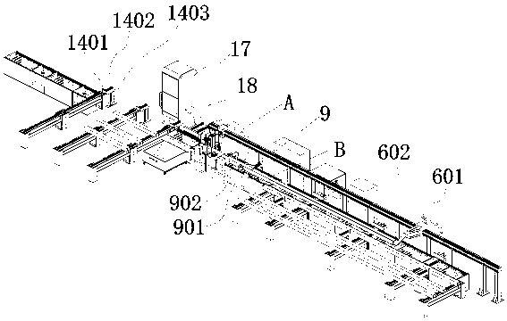
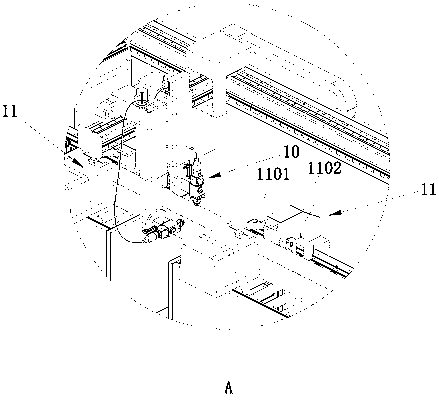
[0085] This embodiment discloses a profile cutting method, refer to Figure 1~Figure 7 , based on the laser cutting automated production line disclosed in embodiment 1, comprising the following steps:

[0086] Step 1: hoisting the profiles 4 to the storage rack 101 for storage by a crane, placing the profiles 4 on the feeding conveyor chain 101111, and keeping the adjacent profiles 4 at intervals;

[0087] Step 2: Loading, the feeding driving motor drives the feeding conveying sprocket group to rotate, and then drives the feeding conveying chain 101111 to move towards the direction close to the feeding platform 102, thereby conveying the profile 4 towards the direction close to the feeding platform 102, After the profile 4 passes through the feeding push plate 502, the feeding lifting member 503 drives the feeding horizontal telescopic member 501 to rise, so that the feeding horizontal telescopic member 501 is higher than the upper surface of the feeding conveyor chain 101111,...


PUM

PropertyMeasurementUnit
Lengthaaaaaaaaaa
Lengthaaaaaaaaaa
Lengthaaaaaaaaaa

Abstract

The invention discloses a profile cutting method for a laser cutting automatic production line, and relates to the field of laser machining. The automatic production line comprises a feeding area, a cutting area and a blanking area, wherein a storage rack and a feeding table are arranged in the feeding area, a side pushing assembly used for pushing profiles to the feeding table is arranged on thestorage rack, the cutting area comprises a feeding end and a discharging end, one end of the feeding table is in butt joint with the feeding end, a forward pushing assembly is further arranged on thefeeding table, the blanking area comprises a first blanking area and a second blanking area, the first blanking area is positioned below the cutting area, and the second blanking area is in butt jointwith the discharging end. According to the method, the blanking area is divided into the first blanking area and the second blanking area, and the blanking of the cut profiles with length less than 1m and the cut profiles with length more than or equal to 1m is carried out through the blanking area and the second blanking area respectively, so that the profiles with different lengths are conveniently cut, classified blanking is carried out, machining is convenient, and the cutting efficiency of the profiles is high.

Description

technical field [0001] The invention relates to the field of laser processing, in particular to a profile cutting method for an automatic laser cutting production line. Background technique [0002] At present, in various machinery manufacturing and processing industries such as machinery and ships, most of the processing of profiles still adopts traditional flame cutting or plasma cutting, which has a low degree of automation, low cutting efficiency, and poor cutting accuracy and section. [0003] Due to the advancement of laser cutting technology, existing technologies also have solutions for profile cutting. [0004] For example, in the prior art, the Chinese invention patent application with the application number 201811192887.3 discloses a profile laser cutting machine and its use method, which includes a frame assembly, a profile conveying mechanism for transporting the profile to be cut, and a clamp for clamping the profile to be cut. The first clamping device, the r...

Claims


Application Information

Patent Timeline
IPC IPC(8): B23K26/38B23K26/70B23K37/04
CPCB23K26/38B23K26/702B23K37/0435
Inventor 文松常勇
Owner FOSHAN HONGSHI LASER TECH CO LTD
Learn More