
A self-adjusting optical fiber cooling device based on centrifugal force transmission

A cooling device and self-adjusting technology, used in manufacturing tools, glass manufacturing equipment, etc., can solve the problems of inability to automatically adjust the degree of optical fiber cooling, insufficient quality of optical fiber cooling, and reduced cooling effect, so as to avoid insufficient cooling and slow down the cooling effect. , the effect of increasing the cooling effect

Active Publication Date: 2022-04-05
江苏科信光电科技有限公司
View PDF0 Cites 0 Cited by
  • Summary
  • Abstract
  • Description
  • Claims
  • Application Information

AI Technical Summary

Problems solved by technology

[0003] The traditional optical fiber cooling is to pass the optical fiber through the cylinder equipped with air-cooling and water-cooling systems, and to speed up the heat dissipation by filling inert gas, while the position of the traditional air-cooling tube and the optical fiber are relatively fixed, so that the same circle The cooling effect of the optical fiber on the cross-section is uneven, which reduces the cooling effect, and the traditional cooling device cannot automatically adjust the cooling degree according to the speed of the optical fiber transportation. When the optical fiber is in contact with the inert gas for too long, it is easy to be affected by gasification air and reduce the quality
[0004] In order to solve the above problems, the inventor provides a self-adjusting optical fiber cooling device based on centrifugal force transmission, which can make the air-cooled tube rotate around the periphery of the optical fiber, thereby making the cooling of the optical fiber more uniform and improving the cooling quality. The cooling effect is adjusted by the speed of optical fiber transmission, which avoids the phenomenon of insufficient optical fiber cooling and the reduction of optical fiber quality due to the influence of vaporized air

Method used


Image

  • A self-adjusting optical fiber cooling device based on centrifugal force transmission
  • A self-adjusting optical fiber cooling device based on centrifugal force transmission
  • A self-adjusting optical fiber cooling device based on centrifugal force transmission

Examples


Embodiment Construction

[0023] The following will clearly and completely describe the technical solutions in the embodiments of the present invention with reference to the accompanying drawings in the embodiments of the present invention. Obviously, the described embodiments are only some, not all, embodiments of the present invention. Based on the embodiments of the present invention, all other embodiments obtained by persons of ordinary skill in the art without making creative efforts belong to the protection scope of the present invention.

[0024] The embodiment of the self-regulating optical fiber cooling device based on centrifugal force transmission is as follows:

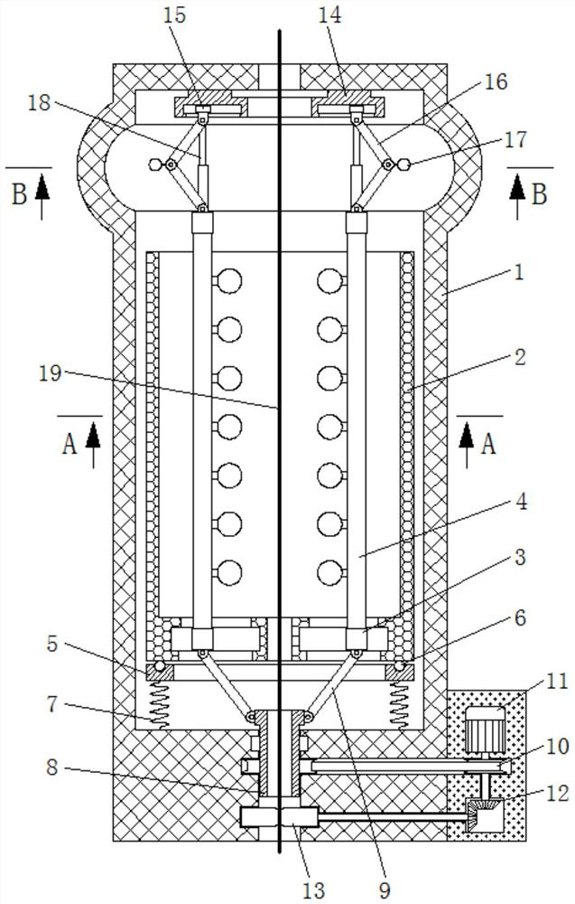
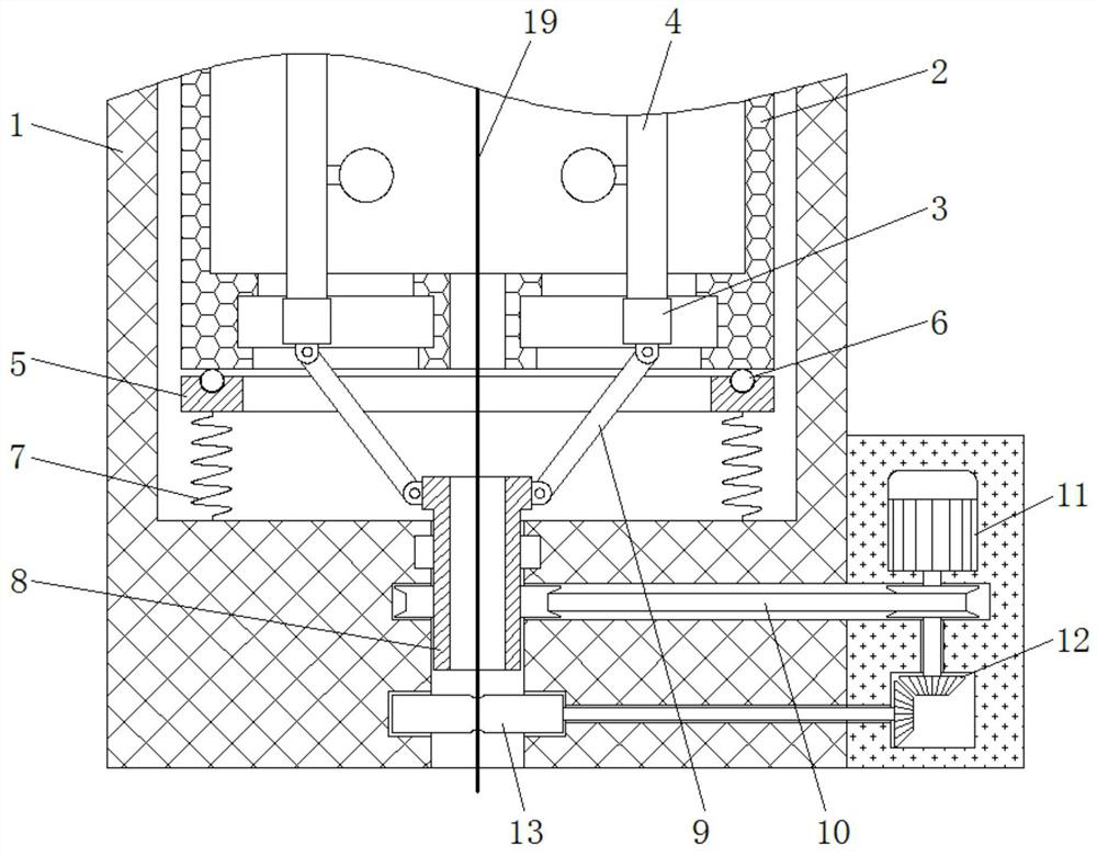
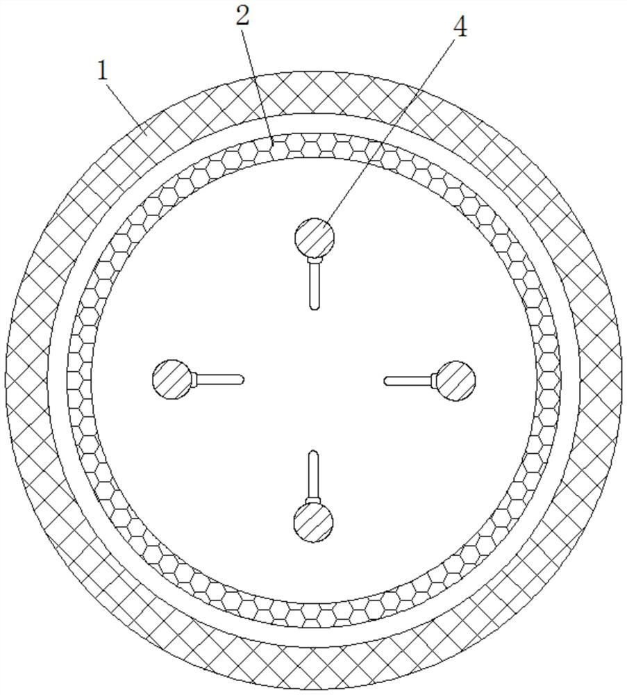
[0025] see Figure 1-5 , a self-adjusting optical fiber cooling device based on centrifugal force transmission, including a cylinder 1, a cylinder 2, a first slider 3, an air-cooled tube 4, a base 5, a ball 6, a spring 7, a rotating seat 8, a connecting rod 9, Belt 10, motor 11, bevel gear 12, delivery roller 13, turntable 14, sec...


PUM


Abstract

The invention provides a self-regulating optical fiber cooling device based on centrifugal force transmission, and relates to the technical field of optical fiber cooling. The self-adjusting optical fiber cooling device based on centrifugal force transmission includes a cylinder, the inside of which is rotatably connected to a drum, and the bottom of the drum is slidably connected to a first slider, and the top of the first slider An air-cooled pipe is fixedly installed, a base is placed on the bottom of the drum, balls are rolled on the top of the base, a spring is fixedly connected to the bottom of the base, and a rotating seat is connected to the bottom of the cylinder for rotation. The self-adjusting optical fiber cooling device based on centrifugal force transmission can make the air-cooled tube rotate around the periphery of the optical fiber, thereby making the cooling of the optical fiber more uniform, improving the quality of cooling, and adjusting the cooling effect according to the speed of optical fiber delivery , to avoid insufficient cooling of the optical fiber and the reduction of the quality of the optical fiber due to the influence of vaporized air.

Description

technical field [0001] The invention relates to the technical field of optical fiber cooling, in particular to a self-adjusting optical fiber cooling device based on centrifugal force transmission. Background technique [0002] Since the optical fiber is obtained by drawing the optical fiber preform, the optical fiber still reaches a high temperature of about 1000°C when it comes out of the furnace, that is, after the optical fiber is formed, it is squeezed in the limited interval from the furnace mouth to the winding station or from the furnace mouth to the outside. The limited section of the package is not enough to reduce the temperature of the optical fiber from about 1000°C to the level similar to the ambient temperature by natural cooling. Therefore, it needs to be cooled before it can enter the next process. [0003] The traditional optical fiber cooling is to pass the optical fiber through the cylinder equipped with air-cooling and water-cooling systems, and fill ine...

Claims


Application Information

Patent Timeline
Patent Type & Authority Patents(China)
IPC IPC(8): C03B37/027
CPCC03B37/02718
Inventor 施杰
Owner 江苏科信光电科技有限公司
Learn More