
Self-rotation gravity platform screen door for labyrinth type shielding structure

A shielding structure and shielding door technology, which is applied in the direction of doors, windows/doors, building components, etc. to protect against harmful radiation, can solve problems such as insufficient shielding effect, difficulty in installing shielded doors, and space and structure limitations, so as to improve space utilization The effect of high efficiency, low processing and assembly cost, simple composition and structure

Active Publication Date: 2020-08-04
NORTHWEST INST OF NUCLEAR TECH
View PDF7 Cites 0 Cited by
  • Summary
  • Abstract
  • Description
  • Claims
  • Application Information

AI Technical Summary

Problems solved by technology

[0003] The present invention solves the problem that the shielding effect of the labyrinth shielding structure used is not sufficient due to the absence of a shielding door at the exit when the radiation experiment is carried out by using the reactor radiation experiment tunnel, but due to space and structure constraints, the installation of the shielding door is difficult. To solve the technical problem, provide a kind of gravity self-rotating shield door for labyrinth shielding structure

Method used


Image

  • Self-rotation gravity platform screen door for labyrinth type shielding structure
  • Self-rotation gravity platform screen door for labyrinth type shielding structure
  • Self-rotation gravity platform screen door for labyrinth type shielding structure

Examples


Embodiment Construction

[0037] The technical solutions of the present invention will be clearly and completely described below in conjunction with the embodiments of the present invention and the accompanying drawings. Apparently, the described embodiments do not limit the present invention.

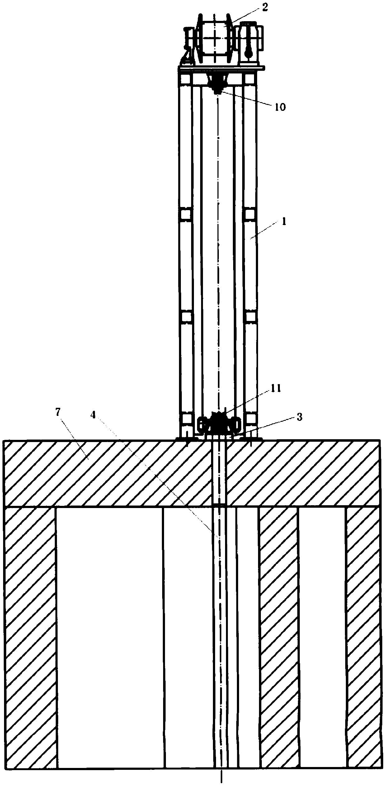
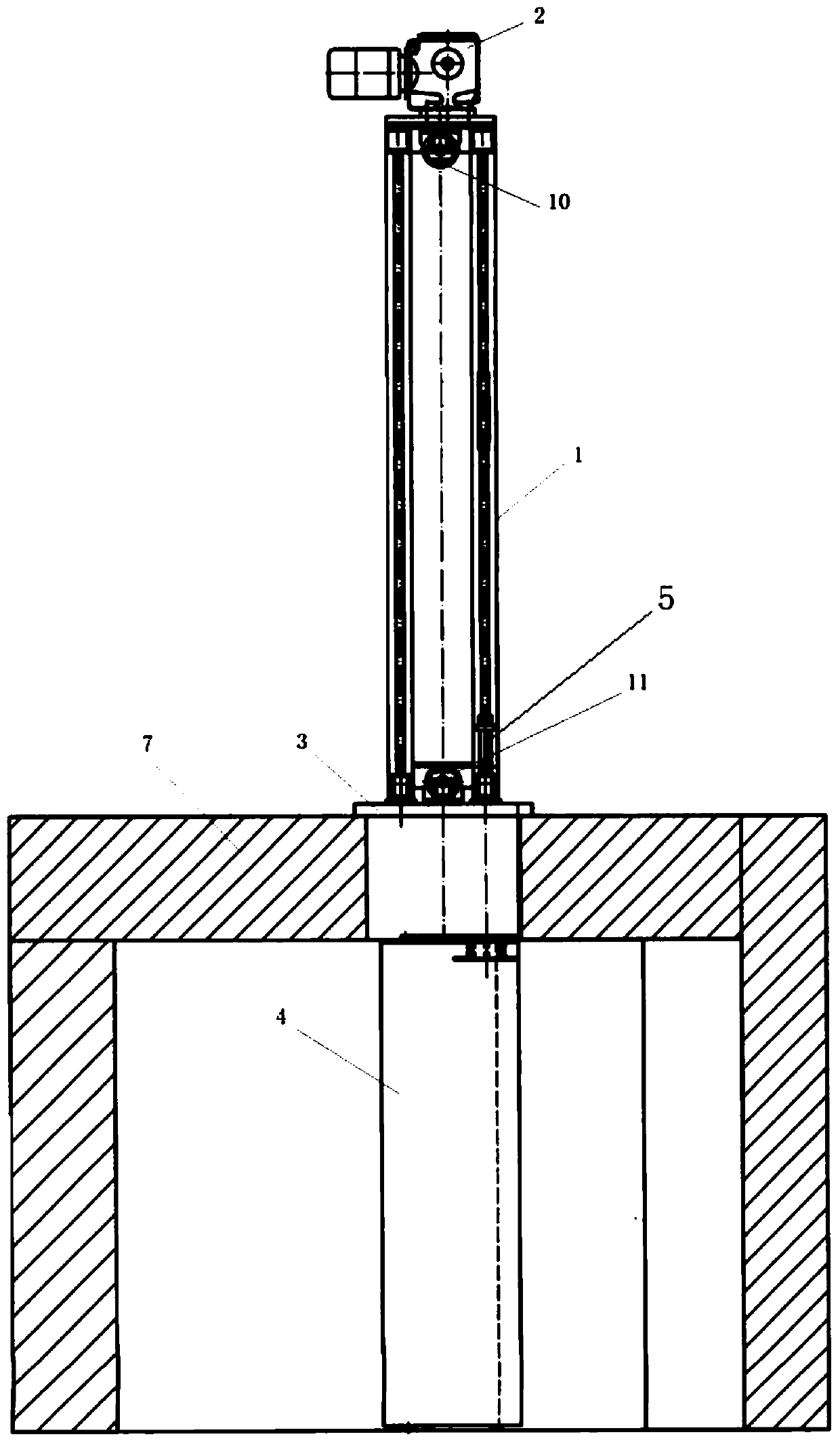
[0038] Such as Figure 1 to Figure 3 , a gravity self-rotating shield door for a labyrinth shield structure, including a bracket 1 , a drive unit 2 , a limit cover 3 , a shield door 4 and a rotating shaft 5 .

[0039] Bracket 1 is fixedly installed on the load-bearing beam 7 at the top of the shielding body. As the installation base point of other components, the shape of bracket 1 is not limited, and can be adjusted according to actual use and assembly requirements to ensure installation reliability and space utilization.

[0040] The driving unit 2 is fixed on the top of the support 1, and the preferred winch is used as the driving unit 2, which is simple in structure and easy to use. When using the winch, th...


PUM


Abstract

The invention belongs to a platform screen door mounting structure, and provides a self-rotation gravity platform screen door for a labyrinth type shielding structure to solve the technical problems of weak shielding effect due to no barrier by platform screen doors at outlets of most labyrinth type shielding structures adopted for traditional irradiation experiments by using reactor irradiation experiment holes and higher mounting difficulty of the platform screen doors due to the space and structure limitations. The self-rotation gravity platform screen door for the labyrinth type shieldingstructure comprises a bracket, a drive unit, a limiting cover plate, a platform screen door, and a rotating shaft; the bracket is mounted on a force bearing beam at the top of a shielding body; the drive unit is fixed on the bracket, and the output end is connected to the limiting cover plate; one end of the rotating shaft is fixedly connected to the platform screen door, and the outer surface ofthe other end is provided with a spiral groove; the height of the spiral groove is 1 / 4 of the pitch; a limiting baffle plate is provided at the end portion, provided with the spiral groove, of the rotating shaft; the limiting cover plate is sleeved outside the rotating shaft; and a slide block matched with the spiral groove is provided on the limiting cover plate.

Description

technical field [0001] The invention belongs to the installation structure of a screen door, in particular to a gravity self-rotating screen door used in a labyrinth screen structure. Background technique [0002] When using the reactor irradiation experiment tunnel to carry out irradiation experiments, strong neutrons and gamma rays will be drawn out. In order to reduce radiation levels to as low as reasonably practicable and to protect the lives of participating and operating personnel, appropriate shielding measures must be taken. At present, a labyrinth shielding structure is mostly used, but since there is no shielding door at the exit of the shielding structure, the shielding effect is still insufficient. However, the inner space of the labyrinth shielding structure is small, and the position where the shielding door is to be installed is perpendicular to the direction of the load-bearing beam on the top of the shielding body, the installation space is limited, and th...

Claims


Application Information

Patent Timeline
IPC IPC(8): E06B5/18E06B3/50
CPCE06B3/5063E06B5/18
Inventor 邬泽鹏马燕苏春磊张文首朱广宁江新标包利红
Owner NORTHWEST INST OF NUCLEAR TECH
Learn More