Double hot corner protection structure and low-temperature storage tank
A hot corner protection, low temperature storage tank technology, applied in fixed capacity gas storage tanks, outer walls of container structures, gas/liquid distribution and storage, etc. Problems such as low temperature damage of the bearing platform, to achieve the effect of less damage, reduced usage, excellent safety and stability
- Summary
- Abstract
- Description
- Claims
- Application Information
AI Technical Summary
Problems solved by technology
Method used
Image

Examples
Embodiment
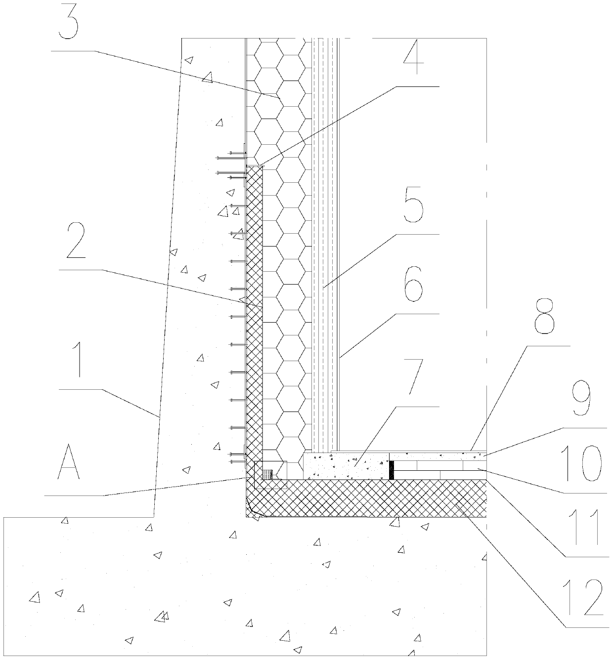
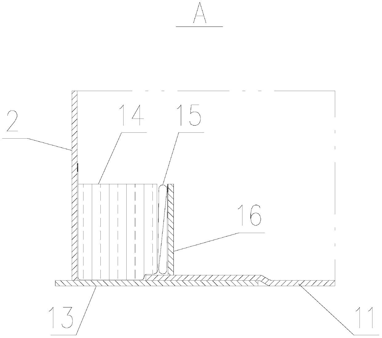
[0023] A dual thermal corner protection structure such as Figure 1 ~ Figure 2 As shown, it is arranged between the inner and outer tanks 1 of the cryogenic storage tank, including the upper hot corner structure and the lower hot corner structure 12;
[0024] The upper hot corner structure includes the hot corner protection wall plate 2 designed around the tank body, the lower edge plate 13, the upper sliding bottom plate 11, the edge baffle 16 and the flexible sealing layer 15; the lower edge plate 13 is tiled to protect the hot corner The wall plate 2 is erected at the end of the lower edge plate 13 close to the outer tank 1, and the thermal angle protection wall plate 2 and the lower edge plate 13 are preferably connected at 90° by welding or other fixing methods; the upper sliding bottom plate 11 is erected on the edge of the lower layer It can slide freely on the board 13. Specifically, the part of the upper sliding bottom plate 11 built on the lower edge plate 13 and its...
PUM
 Abstract
Description
Claims
Application Information