
Laser dynamic focusing system based on paraboloid reflector folded light path

A technology of parabolic reflector and dynamic focusing, which is applied in optics, optical components, instruments, etc., can solve the problems of long response time, slow speed, and limitation of scanning speed of the 3D scanning system, and achieve synchronization, simple control, and synchronous 3D The effect of scanning

Active Publication Date: 2020-08-04
TSINGHUA UNIV
View PDF9 Cites 3 Cited by
  • Summary
  • Abstract
  • Description
  • Claims
  • Application Information

AI Technical Summary

Problems solved by technology

[0004] To sum up, the dynamic focusing technology widely used at present mainly changes the distance between the lens elements of the laser focusing system on the optical path to realize the dynamic change of the focusing position. This method needs to control the movement of the lens along a straight line, and its motion control Compared with the two-dimensional galvanometer scanning, the driving and transmission methods are significantly different, which leads to a great difference in the dynamic performance between the dynamic focusing system and the two-dimensional scanning system, and it is difficult to achieve synchronous control between the two, and the lens is straight There is a large difference in the response speed between the motion and the rotation motion of the scanning galvanometer. The former is slow and has a long response time, which will ultimately limit the scanning speed of the overall 3D scanning system

Method used


Image

  • Laser dynamic focusing system based on paraboloid reflector folded light path
  • Laser dynamic focusing system based on paraboloid reflector folded light path
  • Laser dynamic focusing system based on paraboloid reflector folded light path

Examples


Embodiment Construction

[0022] Below in conjunction with accompanying drawing, the present invention is described in further detail the relevant content of specific structural example and working principle:

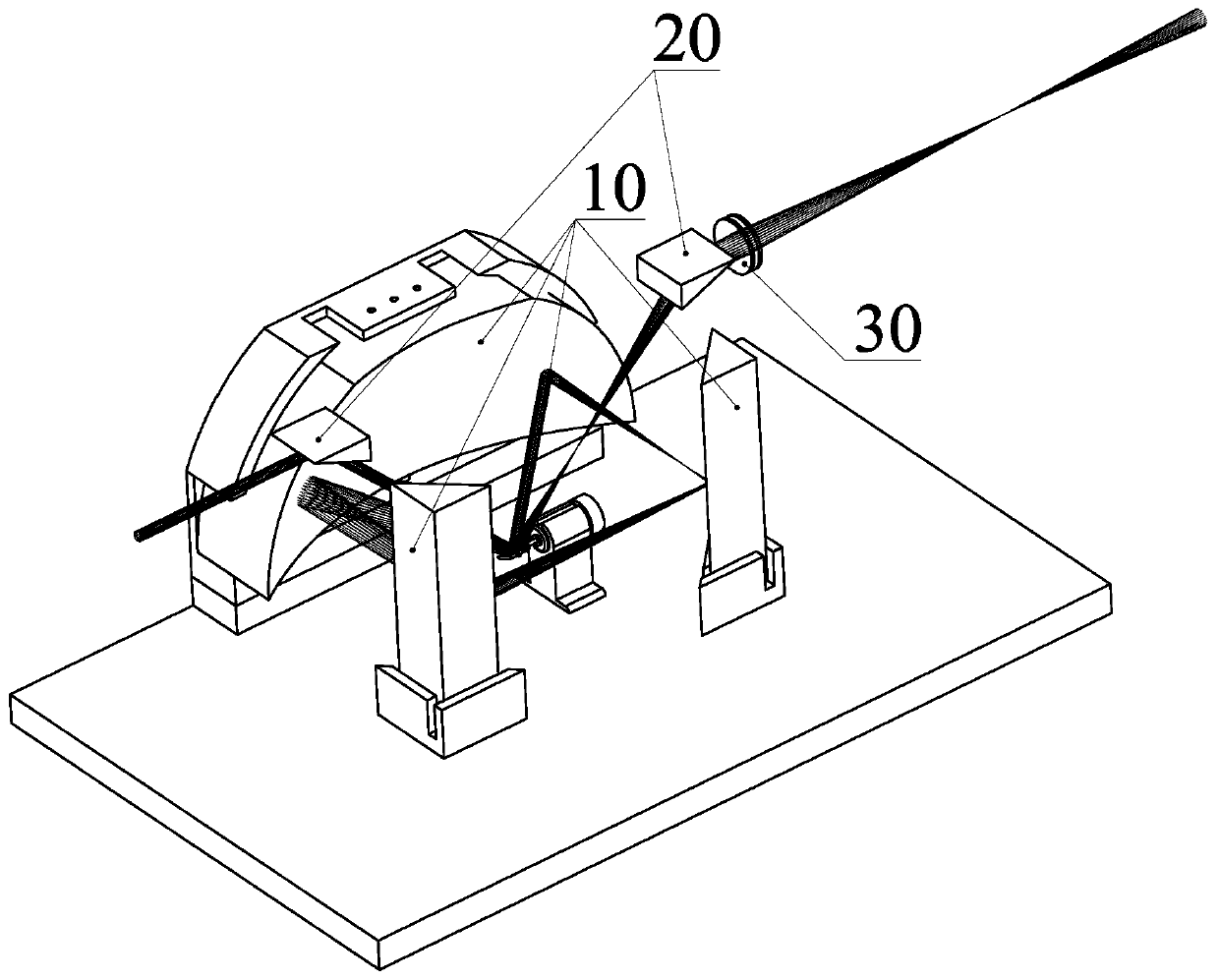
[0023] Such as figure 1 Shown, a kind of laser dynamic focusing system based on parabolic reflector folded optical path, comprises parabolic mirror folded optical path system (10), laser guide mirror (20) and focusing lens group (30); Described laser guide reflector ( 20) Arranged at the optical axis of the (20) incident and outgoing laser light of the parabolic mirror folded optical path system; the focusing lens group (30) is arranged at the outgoing laser light.

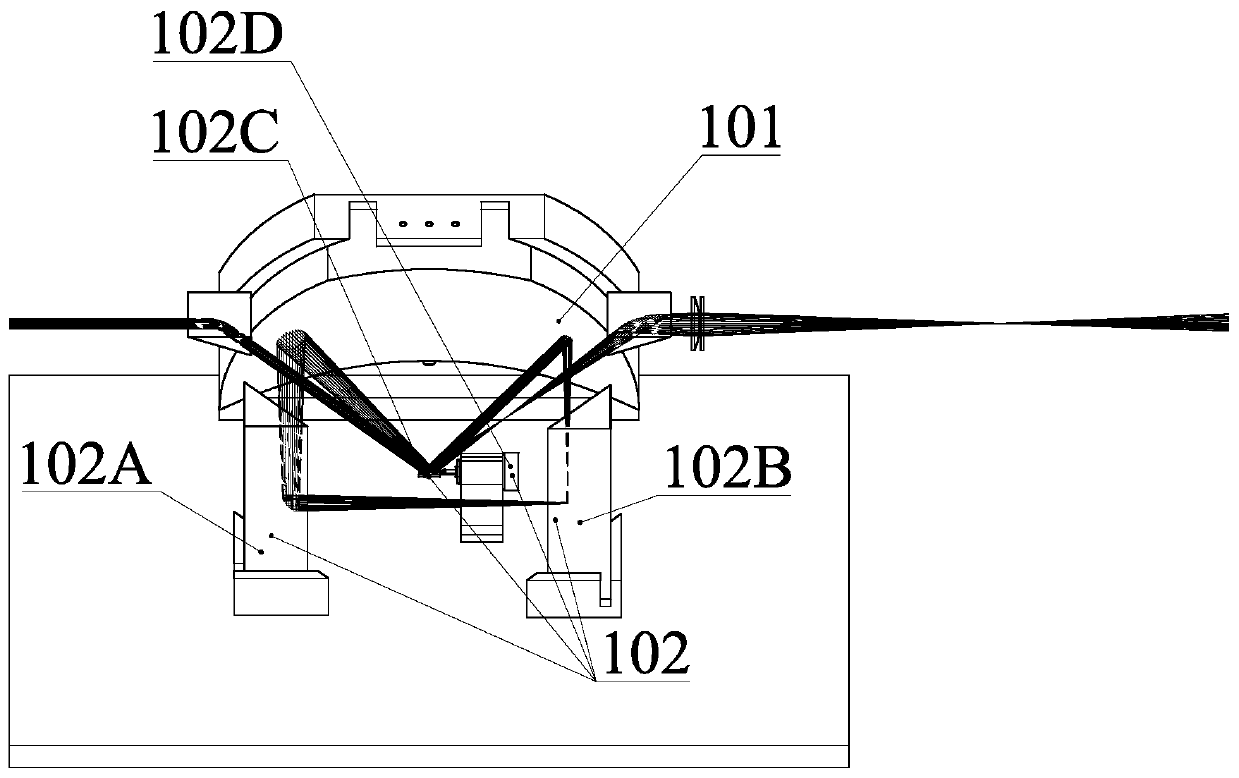
[0024] Such as figure 2 As shown, the parabolic mirror folding optical path system (10) includes a parabolic concave mirror (101) and a folding mirror group (102); wherein, the laser reflection surface of the parabolic concave mirror (101) is a concave paraboloid , which is fixed on the base.

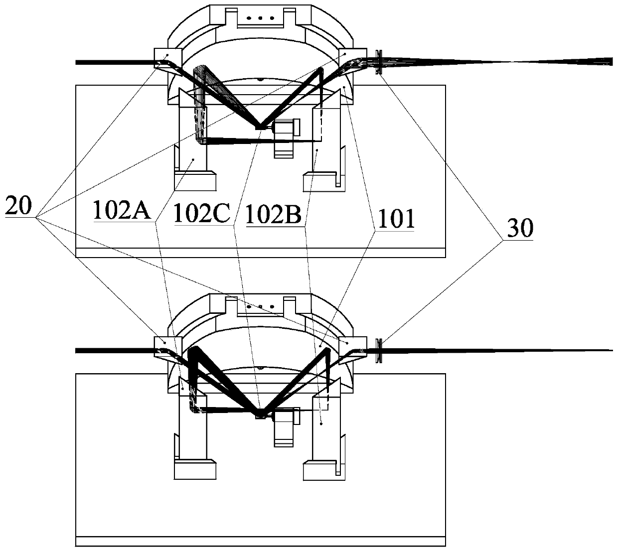
[0025] Such as figure 1 As shown,...


PUM


Abstract

The invention discloses a laser dynamic focusing system based on a paraboloidal mirror folding optical path. The multi-mirror laser dynamic focusing system based on the variable optical path is composed of a paraboloidal mirror folded optical path system, a laser guide mirror and a focusing lens set. A folded light path composed of a plane mirror and a parabolic mirror is adopted to achieve conversion of incident laser of the system, namely, the divergence angle of emergent laser is changed. The folded light path comprises a movable reflector driven by a rotating motor; and the divergence angle of laser emitted by the folded light path can be changed through the change of the inclination angle of the movable reflector, and then different focusing positions are obtained after focusing of afocusing lens. The system realizes dynamic focusing by utilizing the single reflector driven by the rotating motor, has the characteristic of high zooming speed, and can realize high-speed zooming synchronous with the scanning galvanometer.

Description

technical field [0001] The invention relates to a novel laser dynamic focusing principle and system, which changes the divergence angle of laser light exiting the folded optical path of a parabolic reflector through the deflection of a single reflector to realize dynamic focusing, and belongs to the fields of optomechanical integration and laser processing. Background technique [0002] With the rapid development of laser technology, laser scanning technology is widely used in various fields such as surface processing, scanning imaging, rapid prototyping, plate cutting, drilling and so on. Among them, among various laser scanning technologies, galvanometer scanning technology is widely used due to its speed and accuracy. The traditional galvanometer scanning technology mainly combines XY dual-axis galvanometer scanning and field mirror (F-theta lens) to realize the plane range. However, this technology is limited by the field of view of the field lens and it is difficult to ...

Claims


Application Information

Patent Timeline
Patent Type & Authority Applications(China)
IPC IPC(8): G02B26/10
CPCG02B26/105
Inventor 张震余粮
Owner TSINGHUA UNIV
Learn More