
Fingerprint identification device and electronic equipment

A fingerprint recognition and finger technology, which is applied in biometric recognition, character and pattern recognition, acquisition/organization of fingerprints/palmprints, etc. Reduce thickness, improve fingerprint recognition effect, and ensure the effect of fingerprint detection effect

Active Publication Date: 2020-08-04
SHENZHEN GOODIX TECH CO LTD
View PDF6 Cites 6 Cited by
  • Summary
  • Abstract
  • Description
  • Claims
  • Application Information

AI Technical Summary

Problems solved by technology

[0003] Due to the increasing miniaturization of handheld electronic products in the future, the size of the current lens-type under-screen optical fingerprint products is difficult to adapt to this trend, and it is urgent to develop in the direction of thinner thickness, smaller volume, and higher integration.
However, in the existing miniaturization solutions, the image contrast of collimation hole imaging is related to the depth of the collimation hole, and a relatively large depth is required to achieve high imaging quality. At the same time, the light utilization rate of this solution is low.
The solution of using microlens to focus is limited by the technology and lens surface shape. Although the light utilization rate is high, the optical path design is relatively complicated. Moreover, when compatible with other functions, the thickness of the fingerprint recognition device is likely to be too thick, which reduces the practicability.

Method used


Image

  • Fingerprint identification device and electronic equipment
  • Fingerprint identification device and electronic equipment
  • Fingerprint identification device and electronic equipment

Examples


Embodiment Construction

[0062] The technical solutions in the embodiments of the present application will be described below with reference to the accompanying drawings.

[0063] It should be understood that the embodiments of the present application can be applied to optical fingerprint systems, including but not limited to optical fingerprint recognition systems and medical diagnostic products based on optical fingerprint imaging. The embodiment of the application constitutes no limitation, and the embodiment of the present application is also applicable to other systems using optical imaging technology and the like.

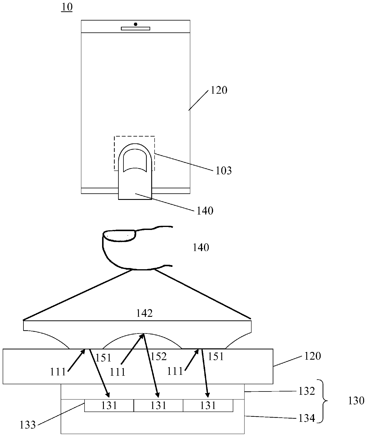
[0064] As a common application scenario, the optical fingerprint system provided by the embodiment of this application can be applied to smartphones, tablet computers, and other mobile terminals with display screens or other terminal devices; more specifically, in the above terminal devices, fingerprint recognition The device may specifically be an optical fingerprint device, which m...


PUM


Abstract

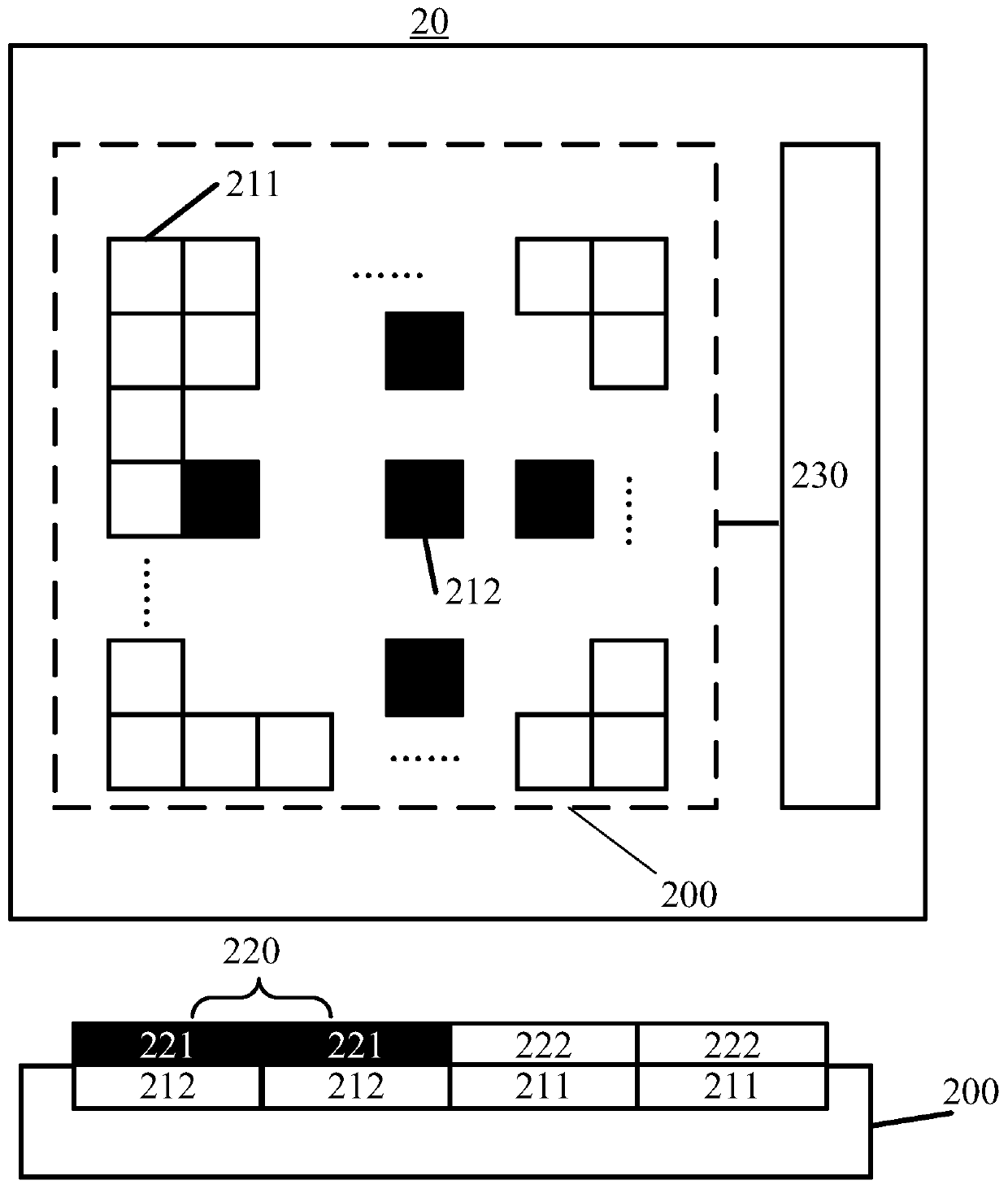
The invention provides a fingerprint identification device and electronic equipment. The fingerprint recognition device sequentially comprises a fingerprint recognition module, a fingerprint recognition module and a control module from top to bottom; the device comprises a micro-lens array, a light filtering unit group array, a first transparent dielectric layer, an infrared light filtering layerand a second transparent dielectric layer, wherein at least one light blocking layer is arranged in the first transparent dielectric layer; each light blocking layer is provided with a small hole array; a metal wiring layer and a pixel unit array positioned below the metal wiring layer are arranged in the second transparent dielectric layer; the metal wiring layer is provided with a diaphragm array corresponding to the pixel unit array, and a preset included angle is formed between a connecting line of a first center of a small hole in the small hole array corresponding to the same pixel unitand a second center of a diaphragm in the diaphragm array and the upper surface of the pixel unit array. According to the fingerprint identification device, a true and false fingerprint identificationfunction can be integrated on the basis of ensuring the fingerprint identification effect, and the universality and the user experience of the fingerprint identification device can be improved on thebasis of lightening and thinning the fingerprint identification device.

Description

[0001] This application requires that the PCT application with the application number PCT / CN2019 / 115443 and the title of the invention "fingerprint identification device and electronic equipment" be submitted to the China Patent Office on November 04, 2019 and submitted to the China Patent Office on November 01, 2019 , the priority of the PCT application with application number PCT / CN2019 / 115162 and title of invention "fingerprint detection device and electronic equipment", the entire contents of which are incorporated in this application by reference. technical field [0002] The present application relates to the technical field of optical fingerprints, and more specifically, to a fingerprint identification device and electronic equipment. Background technique [0003] Due to the increasing miniaturization of handheld electronic products in the future, the size of the current lens-type under-screen optical fingerprint products is difficult to adapt to this trend, and it is ...

Claims


Application Information

Patent Timeline
Patent Type & Authority Applications(China)
IPC IPC(8): G06K9/00
CPCG06V40/1324G06V40/1318G06V40/40H01L25/0655H01L27/14627H01L27/14623H01L27/14625H01L27/14636H10K59/00G02F1/133526G02F1/136209G06V40/1312G06V40/1341
Inventor 张建湘张思超
Owner SHENZHEN GOODIX TECH CO LTD
Learn More