Supercharge Your Innovation With Domain-Expert AI Agents!

Compact omnidirectional antenna having stacked reflector structure

A reflector, base station antenna technology, applied in independent antenna unit combinations, antennas, antenna unit combinations with different polarization directions, etc., can solve problems such as gain drop

Pending Publication Date: 2020-08-04
COMMSCOPE TECH LLC
View PDF1 Cites 0 Cited by
  • Summary
  • Abstract
  • Description
  • Claims
  • Application Information

AI Technical Summary

Problems solved by technology

In the elevation plane, the antenna beam 50 has high gain at elevation angles close to the horizon (e.g., elevation angles between -10° and 10°), but the gain drops off significantly at larger elevation angles above and below the horizon

Method used


Image

  • Compact omnidirectional antenna having stacked reflector structure
  • Compact omnidirectional antenna having stacked reflector structure
  • Compact omnidirectional antenna having stacked reflector structure

Examples


Embodiment Construction

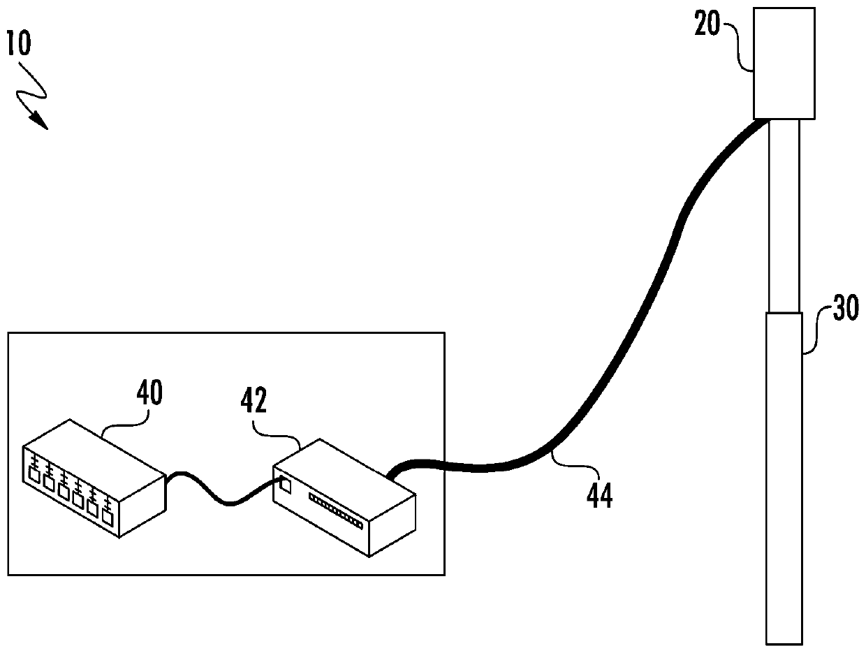
[0026] With the rollout of fifth-generation cellular networks, cellular operators are now interested in small cell base station antennas that include linear arrays of radiating elements operating in two, three, four, or more different frequency bands. array. However, cellular operators also typically have strict form factor requirements for small cell antennas, such as restrictions on the diameter, height, and / or volume of the antenna. Designing small cell antennas that serve two, three, four or more different frequency bands can be challenging while also meeting the form factor requirements specified by cellular operators.

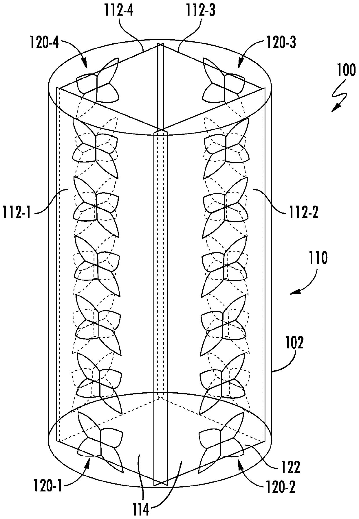
[0027] According to an embodiment of the present invention, a small cell antenna is provided having a reflector assembly comprising a plurality of vertically stacked tubular reflector structures having different horizontal (transverse) cross-sections. A stacked reflector structure may facilitate mounting a linear array of radiating elements operating at ...


PUM


Abstract

The invention relates to a compact omnidirectional antenna with a stacked reflector structure. A base station antenna comprises: a first reflector structure extending along a first longitudinal axis,the first reflector structure having a first cross-section; a second reflector structure extending along a second longitudinal axis, the second reflector structure having a second cross-section different from the first cross-section, the second reflector structure extending above the first reflector structure; a first array of first band radiating elements, which are mounted to extend outwardly from the first reflector structure; a second array of second frequency band radiating elements, which are mounted to extend outwardly from the second reflector structure, the first frequency band not overlapping the second frequency band; and a radome extending around the first reflector structure and the second reflector structure.

Description

technical field [0001] The present invention relates to cellular communication systems, and more particularly, to base station antennas for small cell cellular base stations. Background technique [0002] Cellular communication systems are well known in the art. In a typical cellular communication system, a geographic area is divided into a series of areas, referred to as "cells," and each cell is served by a base station. Typically, a cell may serve users within, for example, 2-20 kilometers from a base station. A base station may include baseband equipment, radio equipment, and antennas configured to provide two-way radio frequency ("RF") communications with fixed and mobile registered users ("subscribers") located throughout a cell. The antennas are typically mounted on towers, wherein the radiation beam ("antenna beam") produced by each antenna is directed outward. Typically, a base station antenna includes one or more phase-controlled arrays of radiating elements, wh...

Claims


Application Information

Patent Timeline
Patent Type & Authority Applications(China)
IPC IPC(8): H01Q15/18H01Q19/10H01Q21/30H01Q1/24
CPCH01Q19/106H01Q21/30H01Q15/18H01Q1/246H01Q5/40H01Q21/26H01Q25/005H01Q21/205H01Q1/42H01Q19/18H01Q21/0025H01Q21/062H04W16/28
Inventor 刘茂生安瑞M·齐莫尔曼P·彼斯勒斯刘朝辉苏瑞鑫唐普亮
Owner COMMSCOPE TECH LLC
Features
  • R&D
  • Intellectual Property
  • Life Sciences
  • Materials
  • Tech Scout
  • Unparalleled Data Quality
  • Higher Quality Content
  • 60% Fewer Hallucinations
Learn More