
Energy generating device utilizing the energy of a flowing medium

A technology of flowing medium and generating equipment, applied in mechanical equipment, mathematical characteristics of engine, engine, etc., can solve problems such as no drive and control unit

Active Publication Date: 2022-04-01
阿提拉科瓦克斯 +1
View PDF15 Cites 0 Cited by
  • Summary
  • Abstract
  • Description
  • Claims
  • Application Information

AI Technical Summary

Problems solved by technology

The invention does not have a drive and control unit

Method used


Image

  • Energy generating device utilizing the energy of a flowing medium
  • Energy generating device utilizing the energy of a flowing medium
  • Energy generating device utilizing the energy of a flowing medium

Examples


Embodiment Construction

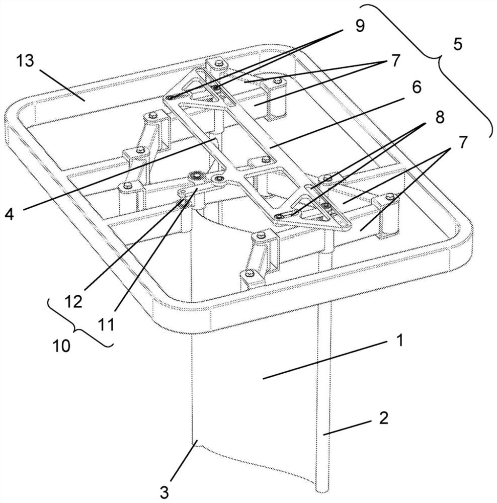
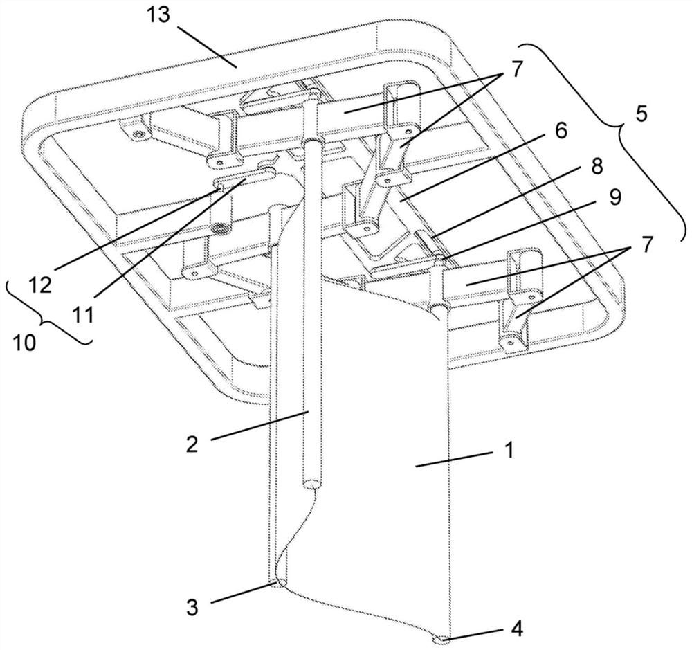
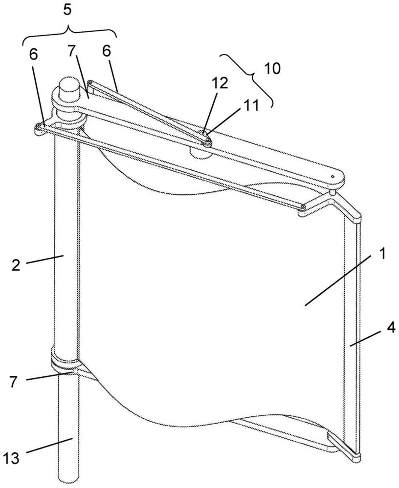
[0031] figure 1 and figure 2 An embodiment is shown in which the device is preferably optimized to utilize hydraulic power. The central element of the device is the undulating element 1, which in this embodiment is fixed in at least two positions, in particular in three positions as shown in the figure like a regular waveform described for example by a sine function . The material of the undulating element 1 may be armor-like, comprising a plurality of rigid or only slightly flexible interconnected materials, preferably metal or plastic or a formable material, preferably a flexible formable material such as metal, plastic or rubber sheet. The material of the undulating element 1 can also be provided with piezoelectric crystals. A fastening element 4 is provided for fixing the undulating element 1 in position; a special embodiment may be the fastening element 4 and the fastening element 4 is implemented as a turbulator element 2 as shown in the figures. The turbulator ele...


PUM


Abstract

The subject of the invention is an energy generating device utilizing the energy of a flowing medium, which has a support structure (13), at least one undulating element (1), at least two fastening elements (4), a drive and control unit (5 ) and an energy recovery and transfer unit (10), wherein the wave element (1) is connected to the fastening element (4), and the drive and control unit (5) is connected to the fastening element (4). It is characterized in that the device comprises at least one turbulator element (2), and the undulation element (1) between two fastening elements (4) is described as a regular waveform determined by a function and comprising at most one complete wave cycle. The subject of the invention is also a method for applying the device.

Description

technical field [0001] The subject of the invention is an energy generating device for harnessing the energy of a flowing medium, the device having a support structure, at least one undulating element and at least two fastening elements to which the undulating element is connected. The invention also includes methods of using the device. Background technique [0002] In the prior art, besides various rotating blade wind turbines, the following solutions are known to exploit the energy of the wind, or in general, the energy of the flowing medium. For example, the specification of Korean Patent No. KR101425302 B1 describes a nano-structured flag that moves in the air due to wind and energy can be extracted from a piezoelectric material in the body of the flag due to the movement. The description does not include instructions related to the use of the inventive device in water and does not enable controlled movement of the flag. [0003] Similarly, Chinese Utility Model No. C...

Claims


Application Information

Patent Timeline
Patent Type & Authority Patents(China)
IPC IPC(8): F03B17/06F03D5/06
CPCF03B17/06F03D5/06F05B2200/261F05B2210/16F05B2250/713B63H1/37F03D5/00F04B43/14F03B17/00F03D5/04F05B2220/706F05B2240/31H02N2/185
Inventor 阿提拉·科瓦克斯蒂博尔·科瓦克斯
Owner 阿提拉科瓦克斯
Learn More