Stable holding type tampon applicator
A tampon, stable technology, applied in tampons, absorbent pads, etc., can solve the problems of easy shaking of the push rod, user discomfort, difficult control of the push rod, etc., to improve structural stability and use safety. performance, improve controllability, and have a good user experience
- Summary
- Abstract
- Description
- Claims
- Application Information
AI Technical Summary
Problems solved by technology
Method used
Image
Examples
Embodiment 1
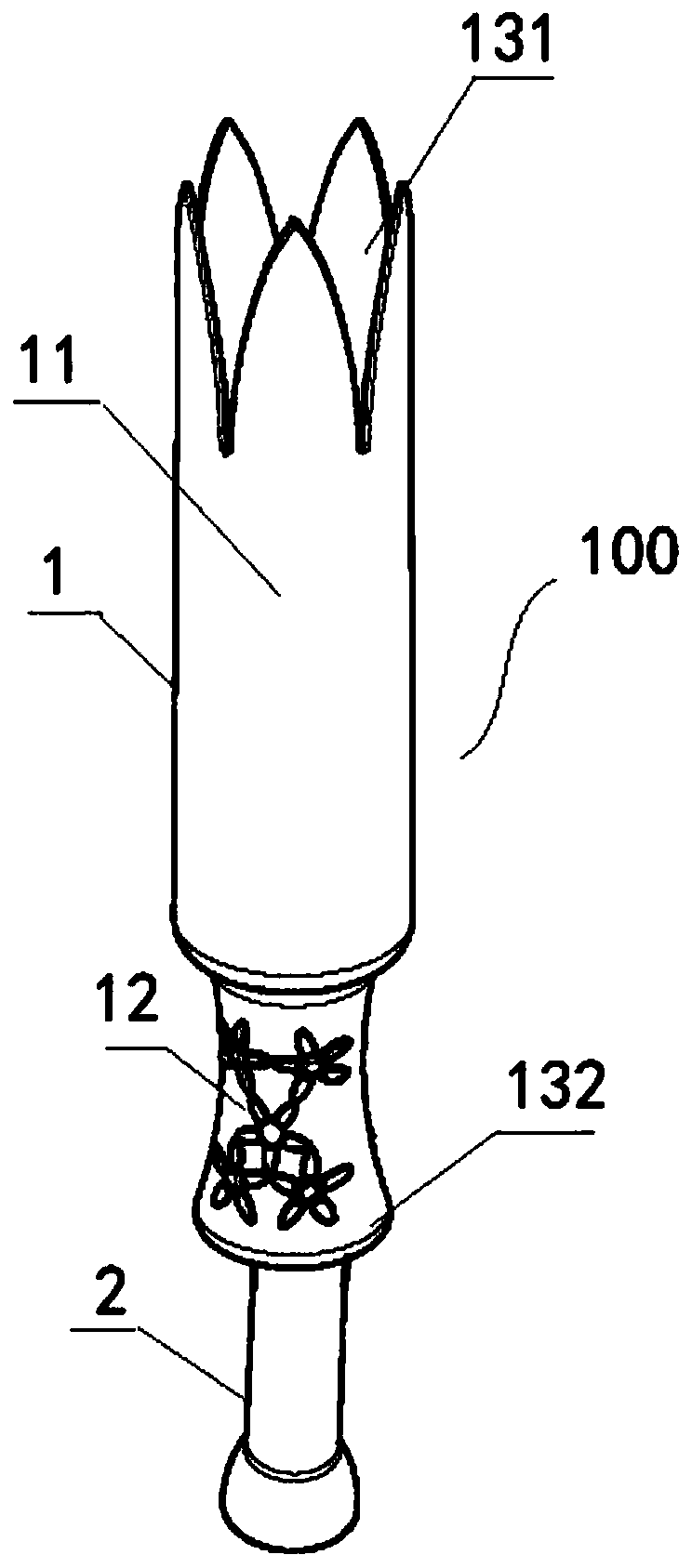
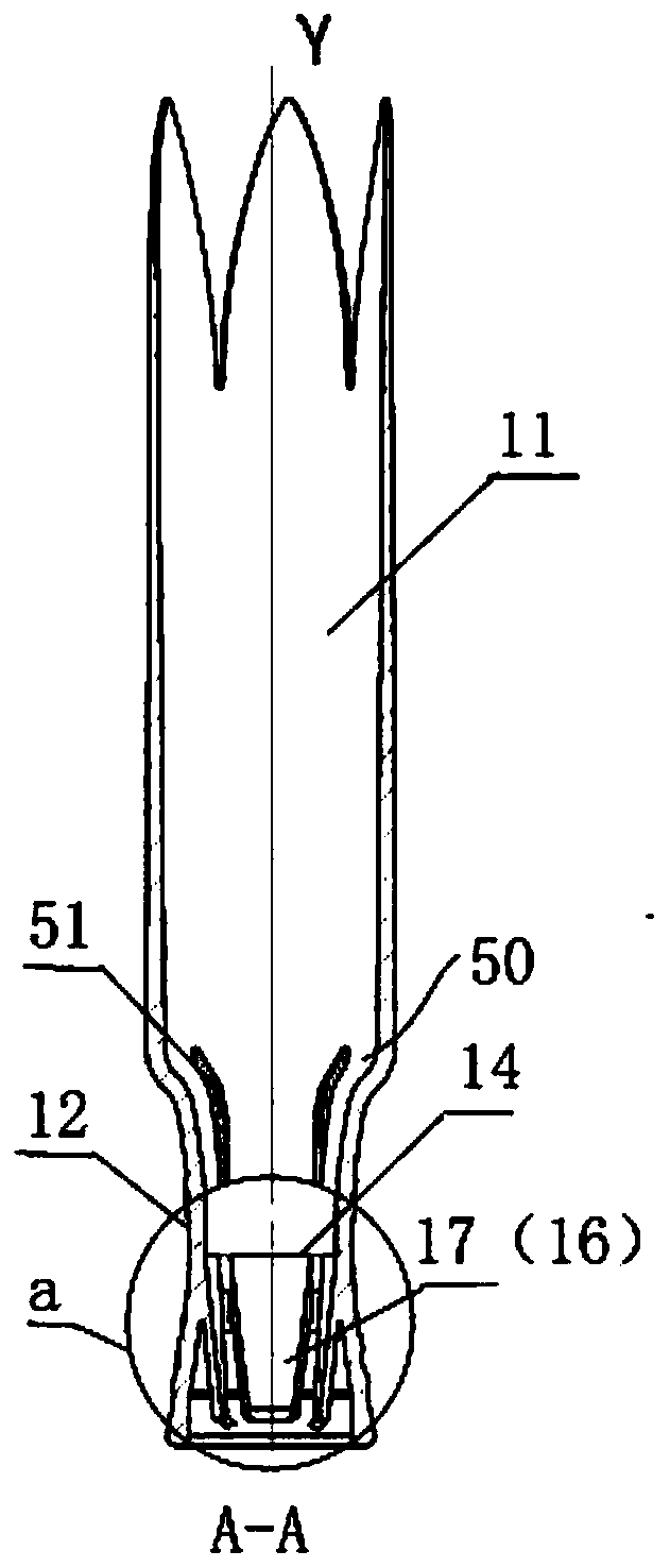
[0039] refer to Figure 1~6 As shown, this embodiment provides a stable tampon applicator 100, including a sleeve 1 and a push rod 2 at least partially pierced in the sleeve 1, and the push rod 2 moves relative to the sleeve 1 to make the tampon The tampon is pushed out. The tampon applicator 100 provided in this embodiment optimizes the structure so that when the user pushes the push rod 2 to push the tampon into the body, the push rod 2 is pushed smoothly and has better controllability, and The running path of the tampon is stable, which can effectively avoid the discomfort caused by the shaking of the tampon.
[0040] Wherein, the sleeve 1 includes a cavity 11 for accommodating a tampon and a handle 12 connected to one end of the cavity 11 . The casing 1 also includes a discharge end 131 at its top for discharging tampons and an insertion end 132 at its tail for insertion of a push rod. The insertion end 132 is connected to the handle 12 . In this embodiment, the discharg...
Embodiment 2
[0050] refer to Figure 7 , this embodiment provides another stable tampon applicator 100, which is similar in structure to the tampon applicator 100 in Embodiment 1, the only difference is that the elastic piece 17' is opposite to the sleeve 1 The centerlines are arranged in parallel, and the elastic piece 17 ′ also includes a bending structure 41 arranged at the free end 19 ′, and the bending structure 41 is movable against the push rod 2 . For the rest of the structure of the tampon applicator 100, please refer to the specific description in Embodiment 1.
[0051] Specifically, the bending structure 41 includes a short side 42 perpendicular to the centerline of the casing 1 and a long side 43 connected at an angle to the short side 42 , and the long side 42 is inclined to the centerline of the casing 1 . As a preference, the angle formed by the long side 43 and the centerline of the casing 1 is [15-60]°. By providing a bending structure 41 at the free end of the elastic p...
Embodiment 3
[0053] refer to Figure 8 , this embodiment provides another stable tampon applicator 100, which is similar in structure to the tampon applicator 100 in Embodiment 1 or 2, the only difference is that the elastic member 16 is a strip Shaped elastic body 17 ". The strip-shaped elastic body 17 "is attached to the inner surface of the handle 12, and includes a first end 51 closer to the cavity 11. The first end 51 is a slope structure, and, in this embodiment, The strip-shaped elastic body 17" is made of silicone material. For the rest of the structure of the tampon applicator 100, please refer to the specific description in Embodiment 1 or 2.
[0054] Because the handle 12 is a concave structure, the strip elastic body 17 "is arranged on its inner surface, so it has the same curvature as the concave structure. As a kind of preference, the thickness of the strip elastic body 17 " is 2 ~ 3mm, At this time, the strip-shaped elastic body 17 " cooperates better with the push rod 2. T...
PUM
| Property | Measurement | Unit |
|---|---|---|
| Thickness | aaaaa | aaaaa |
Abstract
Description
Claims
Application Information
 - R&D Engineer
- R&D Manager
- IP Professional
- Industry Leading Data Capabilities
- Powerful AI technology
- Patent DNA Extraction
Browse by: Latest US Patents, China's latest patents, Technical Efficacy Thesaurus, Application Domain, Technology Topic, Popular Technical Reports.
© 2024 PatSnap. All rights reserved.Legal|Privacy policy|Modern Slavery Act Transparency Statement|Sitemap|About US| Contact US: help@patsnap.com


