Fixing device for part machining

A fixing device and parts processing technology, applied in the field of parts processing, can solve the problems of consuming physical strength and time, reducing the practicability of the device, and the braking effect is not as good as the drum brake, etc., and achieves the effects of high work efficiency, labor saving and wide application range.

Pending Publication Date: 2020-08-07
LIUZHOU RAILWAY VOCATIONAL TECHN COLLEGE
View PDF0 Cites 3 Cited by
  • Summary
  • Abstract
  • Description
  • Claims
  • Application Information

AI Technical Summary

Problems solved by technology

[0002] The brake disc, in simple terms, is a round plate. When the car is moving, it also rotates. The brake caliper clamps the brake disc to generate braking force. When the brake is stepped on, it clamps the brake disc to slow down or stop. , the braking effect of the brake disc is good, and it is easier to maintain than the drum brake. The brakes currently have disc brakes, drum brakes and air brakes. Many older cars have front discs and rear drums. Many cars now have discs at the front and rear. For disc brakes, because the heat dissipation of disc brakes is worse than that of drum brakes, it is not easy to produce heat decay under high-speed braking conditions, so its high-speed braking effect is good, but at low-speed cold brakes, the braking effect is not as good as that of drum brakes
[0003] In real life, when the parts are processed and fixed, the brake discs of the auto parts are usually fixed and polished during the fixing, which is usually fixed by manpower and then polished. This process consumes more physical strength and time. And when manpower is fixed, rollover is prone to occur, because the fixation of the brake disc is not firm, causing it to roll over, and the existing fixing device cannot be adjusted, the brake disc that needs to be processed is limited by size, and then reduces the practicality of the device

Method used


Image

  • Fixing device for part machining
  • Fixing device for part machining
  • Fixing device for part machining

Examples


Embodiment Construction

[0019] The following will clearly and completely describe the technical solutions in the embodiments of the present invention with reference to the accompanying drawings in the embodiments of the present invention. Obviously, the described embodiments are only some, not all, embodiments of the present invention. Based on the embodiments of the present invention, all other embodiments obtained by persons of ordinary skill in the art without making creative efforts belong to the protection scope of the present invention.

[0020] The object of the present invention is to provide a part processing fixture to solve the problems in the prior art.

[0021] In order to make the above objects, features and advantages of the present invention more comprehensible, the present invention will be further described in detail below in conjunction with the accompanying drawings and specific embodiments.

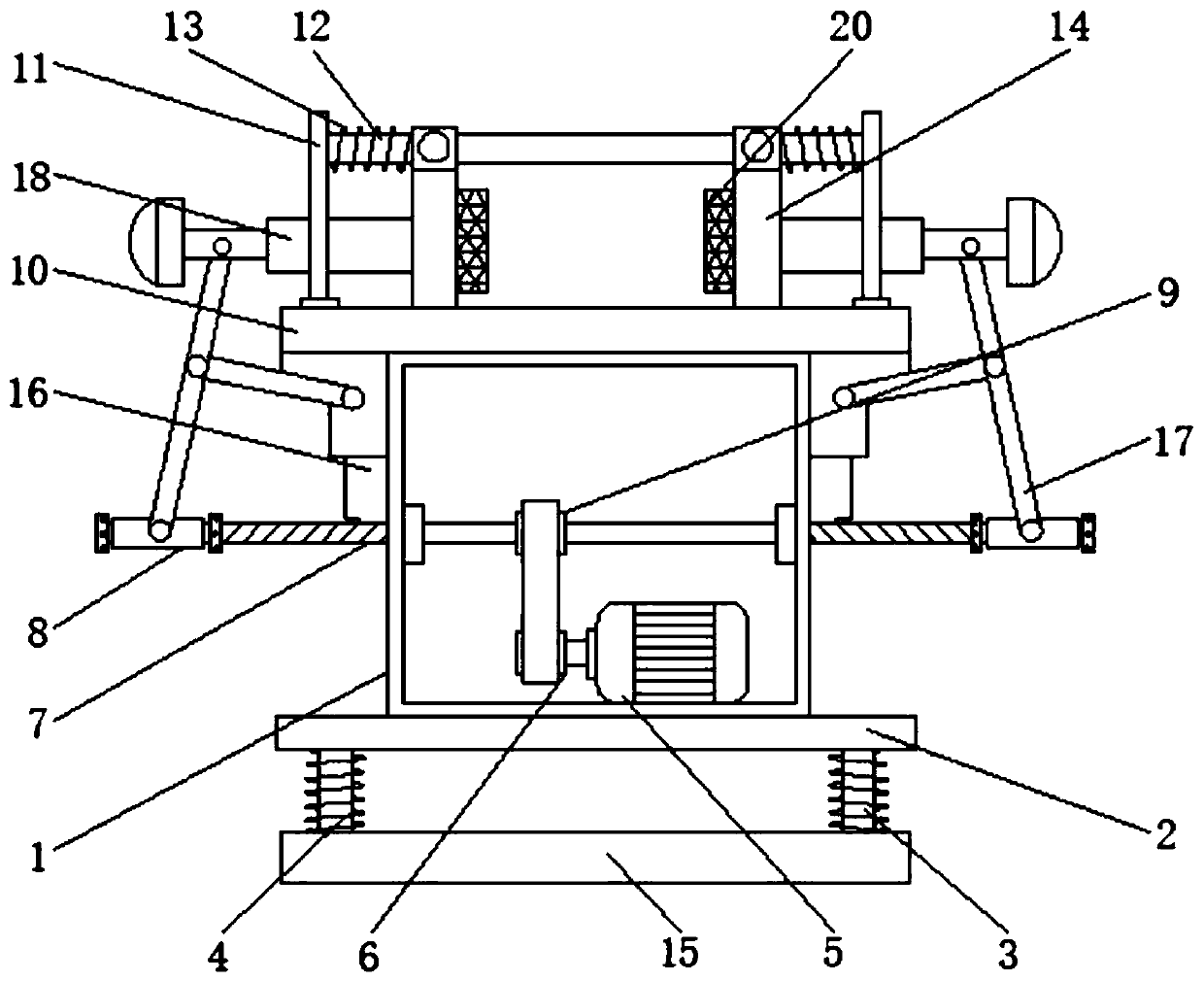
[0022] This embodiment provides a part processing and fixing device, such as figure 1 A...


PUM


Abstract

The invention discloses a fixing device for part machining. The fixing device comprises a base, a control box and an operation table which are sequentially arranged from bottom to top; the two sides of the top of the operation table are each slidably connected with a movable plate; a motor is arranged in the control box, a power output shaft of the motor is in transmission connection with a lead screw, the two ends of the lead screw penetrate through the two side walls of the control box correspondingly to stretch out of the control box, and the two ends of the lead screw are provided with a right-hand thread and a left-hand thread and are in threaded connection with threaded plates; the threaded plates are each connected with a push rod through a T-shaped connecting rod, and the push rodsare arranged on the outer sides of the two movable plates; the motor drives the lead screw to rotate through belt transmission, thus the two threaded plates move in the mode of getting away from eachother, and through transmission of the T-shaped connecting rods, the two push rods are driven to move oppositely; thus the two movable plates are driven to move oppositely, parts between the two movable plates are clamped in a contact mode, the parts are automatically clamped, manual fixing is not needed, the parts are fixed stably, the parts with various sizes can be fixed, and the practicability is high.

Description

technical field [0001] The invention relates to the technical field of part processing, in particular to a part processing and fixing device. Background technique [0002] The brake disc, in simple terms, is a round plate. When the car is moving, it also rotates. The brake caliper clamps the brake disc to generate braking force. When the brake is stepped on, it clamps the brake disc to slow down or stop. , the braking effect of the brake disc is good, and it is easier to maintain than the drum brake. The brakes currently have disc brakes, drum brakes and air brakes. Many older cars have front discs and rear drums. Many cars now have discs at the front and rear. For disc brakes, because the heat dissipation of disc brakes is worse than that of drum brakes, it is not easy to produce thermal recession under high-speed braking conditions, so its high-speed braking effect is good, but at low-speed cold brakes, its braking effect is not as good as that of drum brakes. [0003] In r...

Claims


Application Information

Patent Timeline
Patent Type & Authority Applications(China)
IPC IPC(8): B24B41/06
CPCB24B41/06
Inventor 林新罗建韦德周黄文锋黄有珑覃建欣
Owner LIUZHOU RAILWAY VOCATIONAL TECHN COLLEGE
Why Eureka
Try Eureka