Plastic board printing equipment
A technology for printing equipment and plastic plates, applied in printing, printing presses, rotary printing presses, etc., can solve the problems of cumbersome operation process, labor-intensive, low work efficiency, etc., and achieve the effect of simple operation, improving work efficiency and saving manpower
- Summary
- Abstract
- Description
- Claims
- Application Information
AI Technical Summary
Problems solved by technology
Method used
Image

Examples
Embodiment 1
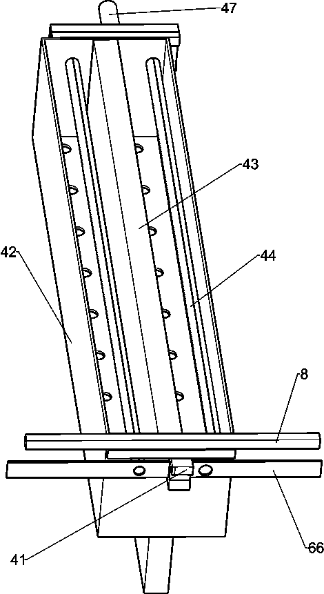
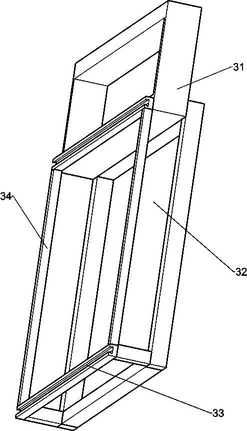
[0026] A plastic plate printing equipment such as Figure 1-4 As shown, it includes a frame 1, a lower mold assembly 2, an upper mold assembly 3, a scraper assembly 4 and a baffle 5, the left and right sides of the frame 1 are connected with baffles 5, and the lower part of the frame 1 is provided with a lower The mold assembly 2 is provided with an upper mold assembly 3 on the upper part of the frame 1, and the upper mold assembly 3 is provided with a scraper assembly 4.
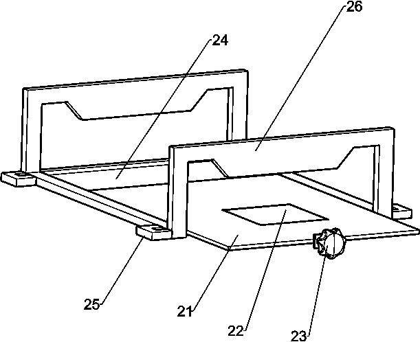
[0027] The lower mold assembly 2 includes a lower mold 21, a star handle 23, a support plate 24, a sliding block 25 and a wedge block 26. The left and right sides of the lower part of the frame 1 are slidably connected with the sliding block 25, and the two sides of the sliding block 25 There is a support plate 24 connected between them, wedge-shaped blocks 26 are connected to the front and rear sides of the top of the support plate 24, the lower mold 21 is slidingly connected to the support plate 24, and t...
Embodiment 2
[0032] On the basis of Example 1, such as Figure 4-5 As shown, a drive assembly 6 is also included, and the drive assembly 6 includes a motor 61, a dye barrel 62, a second dye pipe 63, a threaded rod 64, a threaded sleeve 65, a material baffle 66 and a second spool 67, and the frame 1 A motor 61 is installed on the left side of the top rear side, and a dye barrel 62 is slidably connected to the rear side of the top of the frame 1. The dye tube 63 is connected with a threaded rod 64 on the output shaft of the motor 61, and the threaded rod 64 is rotatably matched with the frame 1. The threaded rod 64 is threadedly connected with a threaded sleeve 65, and the threaded sleeve 65 is connected with the dye barrel 62, and the rear side slides Block 41 is slidably connected with a baffle plate 66, the left and right sides of the baffle plate 66 are provided with through grooves, and the discharge ends of the second dye pipe 63 on both sides cooperate with the through grooves on both...
PUM
 Abstract
Description
Claims
Application Information
 - R&D
- Intellectual Property
- Life Sciences
- Materials
- Tech Scout
- Unparalleled Data Quality
- Higher Quality Content
- 60% Fewer Hallucinations
Browse by: Latest US Patents, China's latest patents, Technical Efficacy Thesaurus, Application Domain, Technology Topic, Popular Technical Reports.
© 2025 PatSnap. All rights reserved.Legal|Privacy policy|Modern Slavery Act Transparency Statement|Sitemap|About US| Contact US: help@patsnap.com