Necking-down type combustion chamber

A combustion chamber, constriction type technology, applied in combustion engines, internal combustion piston engines, engine components, etc., can solve the problems of weak intake vortex and compression vortex, insufficient oil and gas mixing, and unsatisfactory combustion quality, so as to improve the ignition quality. Stability, the effect of accelerating the burning speed

Pending Publication Date: 2020-08-07
DONGFENG COMML VEHICLE CO LTD
View PDF1 Cites 0 Cited by
  • Summary
  • Abstract
  • Description
  • Claims
  • Application Information

AI Technical Summary

Problems solved by technology

[0002] At present, the piston combustion chamber of the gas engine is mainly a straight piston combustion chamber, and its intake vortex and compression vortex are relatively weak, resulting in low combustion tumble and turbulent intensity, insufficient oil-gas mixing, and unsatisfactory combustion quality
In order to make the gas burn quickly and fully in the combustion chamber, the researchers tried to increase the squeeze flow area of ​​the piston by shrinking the mouth, strengthen the flow in the cylinder, increase the turbulent kinetic energy, and accelerate the combustion speed, such as the Chinese utility model patent with application number 201520598758.X In the disclosed combustion chamber of a piston of a gas engine, the mouth of the body is provided wit

Method used


Image

  • Necking-down type combustion chamber
  • Necking-down type combustion chamber
  • Necking-down type combustion chamber

Examples


Embodiment 1

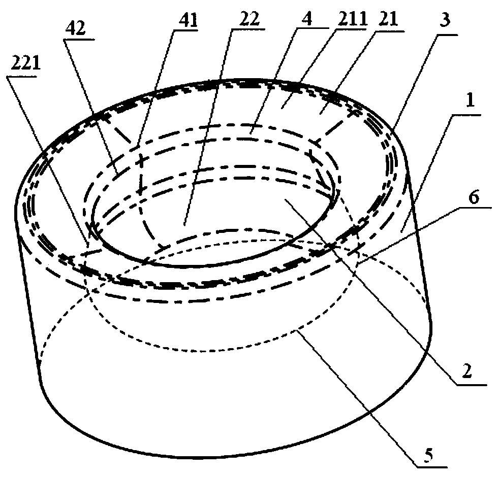
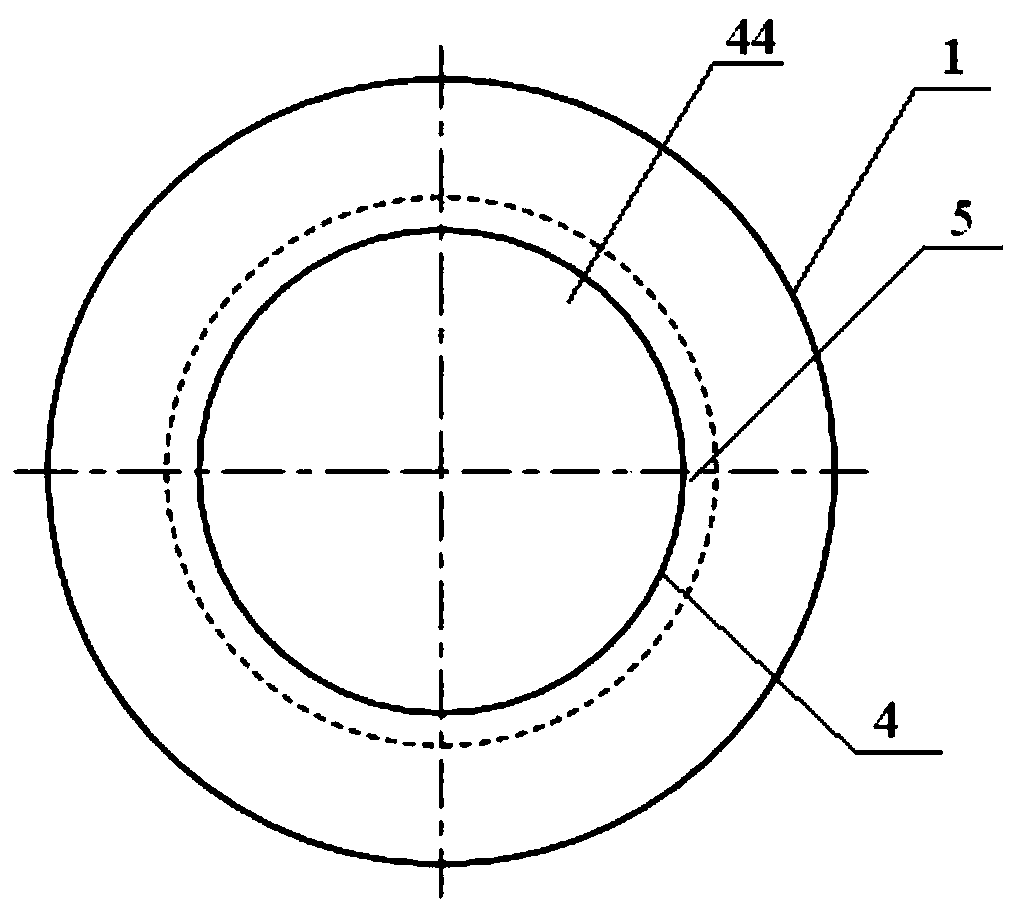
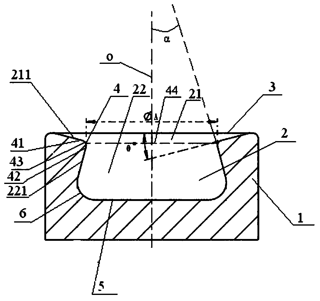
[0021] combine figure 1 As shown, the necking-type combustion chamber of the present embodiment includes a combustion chamber 2 extending from the top surface of the piston 1 to the inside of the piston 1, and the combustion chamber 2 includes an opening 3 located on the top surface of the combustion chamber 2, and an opening 3 located in the middle of the combustion chamber 2. The throat 4 and the bottom surface 5 at the bottom of the combustion chamber 2, the central axis of the combustion chamber 2 coincides with the central axis o of the piston.

[0022] Concrete combination figure 2 with image 3 As shown, the throat 4 includes an upper edge 41 of the throat along its axial direction, a lower edge 42 of the throat, and an annular arc-shaped protrusion 43 transitionally connecting the upper edge 41 of the throat and the lower edge 42 of the throat, and along its radial direction. The throat opening 44, the longitudinal section of the annular arc-shaped protrusion 43 is ...

Embodiment 2

[0027] combine figure 1 , figure 2 with Figure 4 As shown, the difference between Embodiment 2 and Embodiment 1 lies in the shape of the flow guide side wall 211. In this embodiment, the longitudinal section of the flow guide side wall 211 is an upwardly convex arc shape.

[0028] Compared with the constricted combustion chamber with the application number 201520598758.X, in the constricted combustion chamber of this embodiment, the diversion side wall of the diversion cavity is designed so that the diameter gradually increases from the throat to the opening The convex curved surface guides the squeeze flow directly into the combustion chamber through the diversion effect of the diversion side wall in the shape of the convex curved surface, avoiding the excessive flow velocity near the spark plug to hinder the formation of the fire core, increasing the turbulent flow intensity in the combustion chamber, and accelerating the combustion speed.

Embodiment 3

[0030] combine figure 1 , figure 2 with Figure 5 As shown, the difference between Embodiment 2 and Embodiment 1 lies in the shape of the flow guide side wall 211 . In this embodiment, the longitudinal section of the flow guide side wall 211 is a downwardly concave arc shape.

[0031] Compared with the constricted combustion chamber with the application number 201520598758.X, in the constricted combustion chamber of this embodiment, the diversion side wall of the diversion cavity is designed so that the diameter gradually increases from the throat to the opening The concave curved surface guides the squeeze flow directly into the combustion chamber through the diversion effect of the diversion side wall in the shape of the concave curved surface, avoiding the excessive flow velocity near the spark plug to hinder the formation of the fire core, increasing the turbulent flow intensity in the combustion chamber, and accelerating the combustion speed.


PUM

PropertyMeasurementUnit
Corner radiusaaaaaaaaaa

Abstract

The invention relates to the field of engines, in particular to a necking-down type combustion chamber. The necking-down type combustion chamber comprises a combustion chamber body. The combustion chamber body comprises an opening, a throat and a bottom face. The throat comprises a throat upper edge, a throat lower edge, an annular arc protrusion and a throat opening part. The plane where the throat opening part is located divides the combustion chamber body into an upper-layer flow guiding cavity and a lower-layer combustion cavity. The flow guiding cavity is defined by a flow guiding side wall arranged between the opening and the throat upper edge. The flow guiding side wall gradually outwards extends to the opening from the throat upper edge. The combustion cavity is defined by a combustion side wall arranged between the throat lower edge and the bottom face, and the combustion side wall gradually shrinks to the throat lower edge from the bottom face. The throat opening part is in acircular shape, and the bottom face is a circular flat bottom face. Through the flow guiding action of the flow guiding cavity, extrusion flow is guided to directly flow into the combustion chamber body, the ignition stability is improved, and the combustion speed is increased.

Description

technical field [0001] The invention relates to the field of engines, in particular to a necking type combustion chamber. Background technique [0002] At present, the piston combustion chamber of the gas engine is mainly a straight piston combustion chamber, and its intake vortex and compression vortex are relatively weak, resulting in low combustion tumble and turbulent intensity, insufficient oil-gas mixing, and unsatisfactory combustion quality. In order to make the gas burn quickly and fully in the combustion chamber, the researchers tried to increase the squeeze flow area of ​​the piston by shrinking the mouth, strengthen the flow in the cylinder, increase the turbulent kinetic energy, and accelerate the combustion speed, such as the Chinese utility model patent with application number 201520598758.X In the disclosed combustion chamber of a piston of a gas engine, the mouth of the body is provided with a throat fillet protruding from the side wall of the body to the ce...

Claims


Application Information

Patent Timeline
IPC IPC(8): F02B23/00F02F3/26F02F3/28
CPCF02B23/00F02F3/26F02F3/28Y02T10/12
Inventor 徐敏胡晶晶张娜向辉吕昌富龚远飞
Owner DONGFENG COMML VEHICLE CO LTD
Why Eureka
Try Eureka