Eureka AIR delivers breakthrough ideas for toughest innovation challenges, trusted by R&D personnel around the world.

Multifunctional ball valve

A multi-functional, ball valve technology, applied in multi-way valves, valve details, valve devices, etc., can solve problems such as shortening the service life of ball valves, internal leakage of ball valves, and sealing failure, so as to achieve automatic control, avoid contact friction, and reduce rotation The effect of torque

Inactive Publication Date: 2020-08-07
李军
View PDF0 Cites 1 Cited by
  • Summary
  • Abstract
  • Description
  • Claims
  • Application Information

AI Technical Summary

Problems solved by technology

In this way, the torque is large when opening and closing, and the ball will rub against the valve seat during the rotation process, which will cause serious wear and tear, which will easily cause leakage, reduce the working reliability of the ball valve, and shorten the service life of the ball valve;
[0006] (2) In the actual working process, the pipeline conveying medium will contain various impurities. During the switching process of the ball valve, because the ball and the valve seat are always in close contact, the sealing surface is easily scratched by harder impurities, resulting in seal failure and causing The ball valve leaks internally, so the ball valve needs frequent maintenance and replacement
However, since the traditional ball valve must be repaired by dismantling the entire ball valve and the pipeline, not only the maintenance is very troublesome, but also the normal use of the pipeline will be delayed, and the medium in the pipeline on both sides will flow out, polluting the working environment;
[0007] (3) The existing traditional ball valves cannot achieve throttling and flow control. In order to adjust the flow in the pipeline, an additional flow regulating valve needs to be added to the pipeline, which increases the configuration cost of the pipeline.

Method used


Image

  • Multifunctional ball valve
  • Multifunctional ball valve
  • Multifunctional ball valve

Examples


Embodiment Construction

[0046] The technical solutions of the present invention will be further described in detail below in conjunction with the accompanying drawings and embodiments.

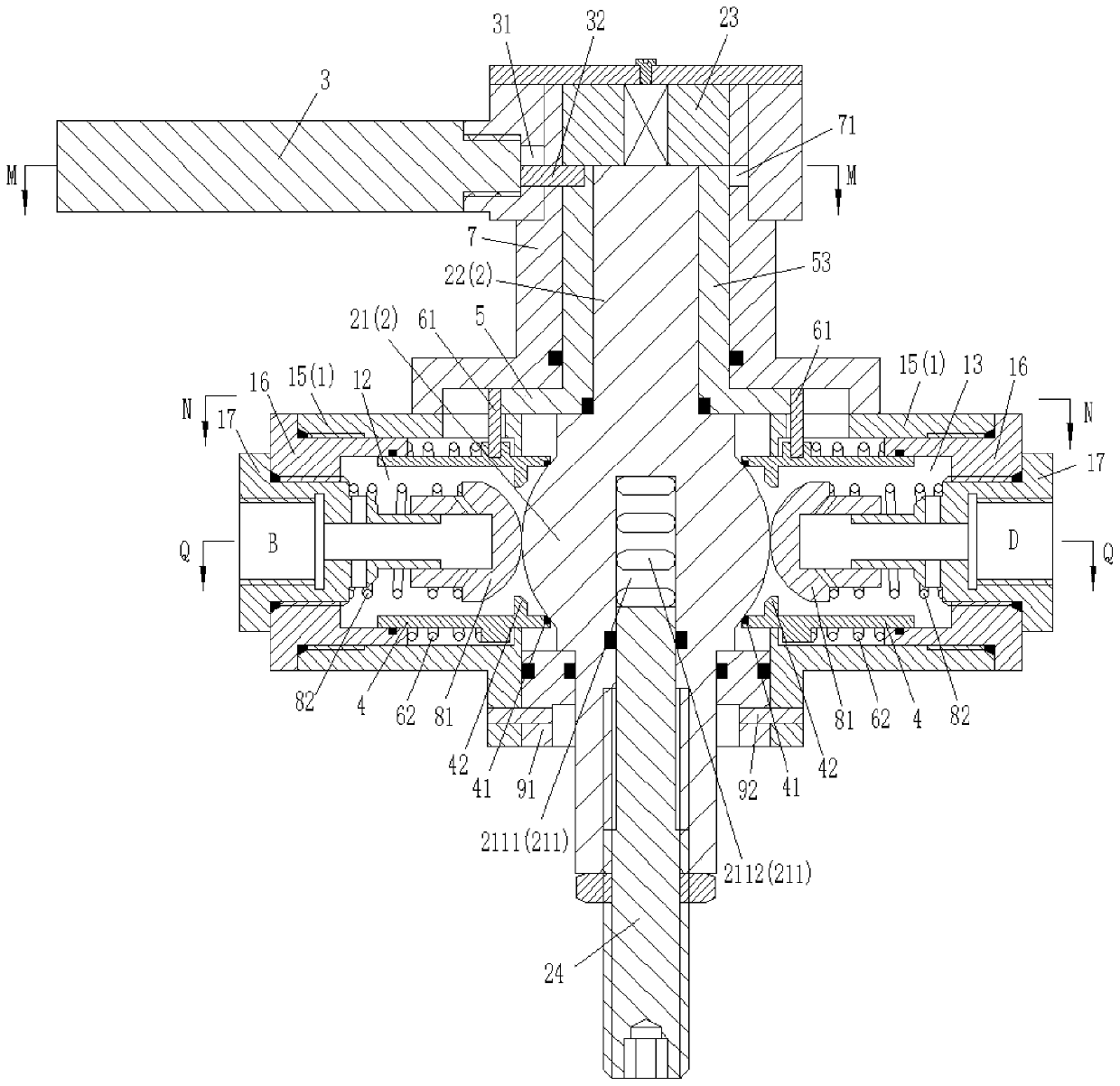
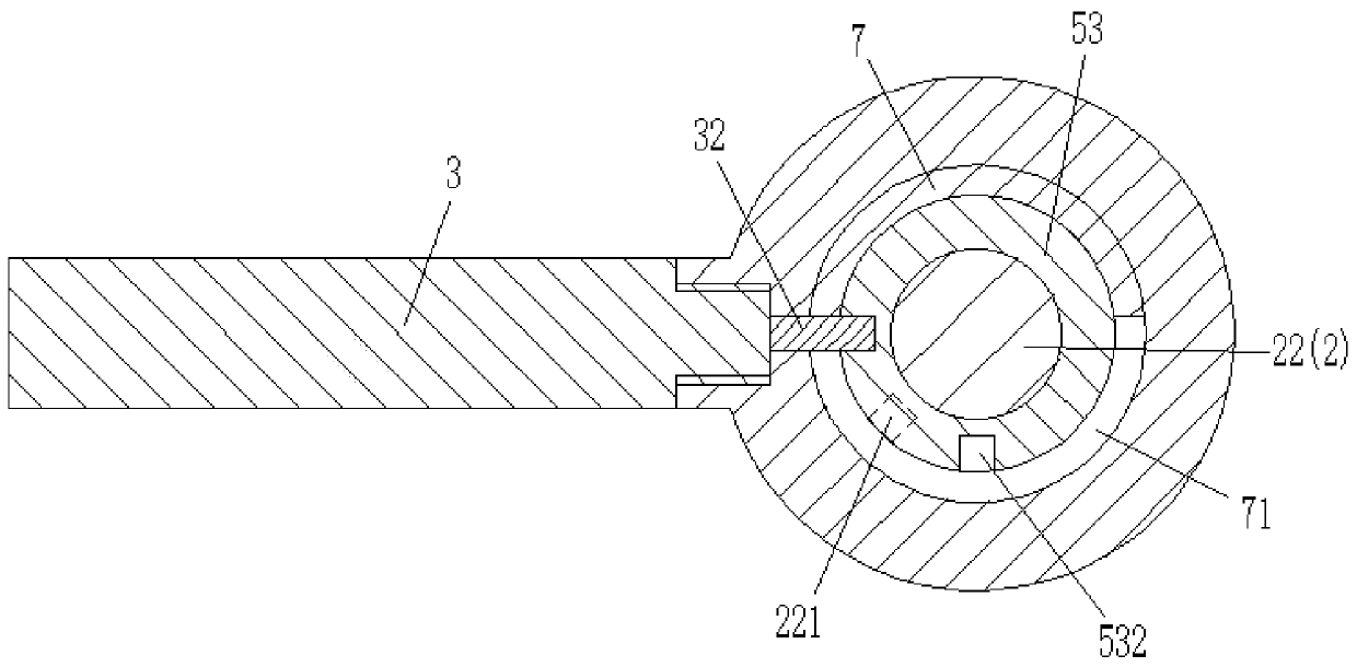
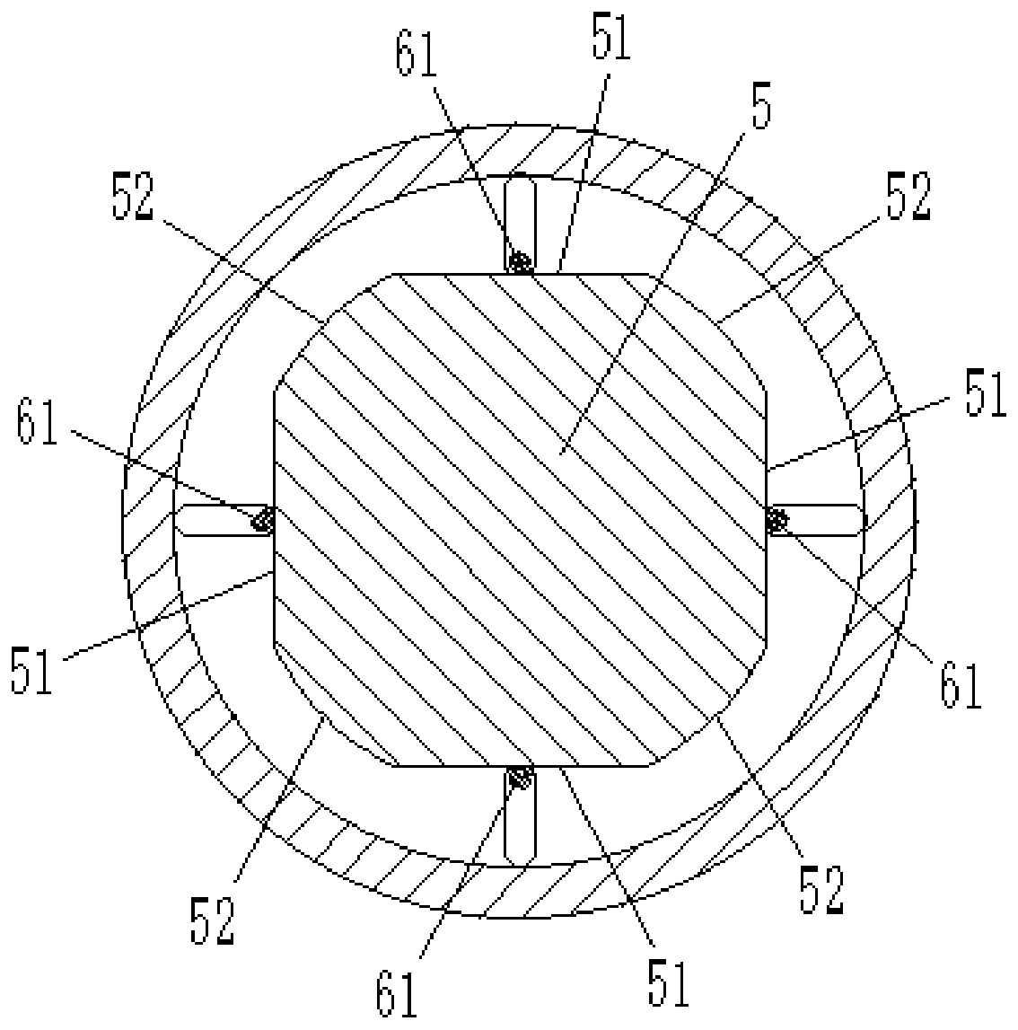
[0047] combine Figure 1 to Figure 8 As shown, the multifunctional ball valve of this embodiment includes a valve body 1 , a valve ball 2 , a handle 3 and a valve seat 4 . The valve body 1 is provided with port A, port B, port C and port D uniformly distributed along the circumferential direction, and inside the valve body 1 there are four first The control chamber 11, the second control chamber 12, the third control chamber 13 and the fourth control chamber 14, and the four control chambers communicate with port A, port B, port C and port D respectively.

[0048] The valve ball 2 is located inside the valve body 1 and consists of a fixedly connected ball 21 and a connecting end 22 . Wherein, the ball 21 is located at the intersection of the four control chambers and has a through hole 211 along its radial directio...


PUM


Abstract

The invention belongs to the technical field of pipeline valves, and discloses a multifunctional ball valve. The multifunctional ball valve comprises a valve body, a valve ball, a handle and a valve seat; the valve body is provided with an A port, a B port, a C port and a D port and four control chambers respectively communicating with the A port, the B port, the C port and the D port; the valve ball is composed of a ball body and a connecting end; the ball body is provided with a through hole in the radial direction and is located at an intersection position of the four control chambers; theconnecting end is connected with the handle, and the over-flow area of the through hole is adjustable; the valve seat is arranged in the control chambers, and the valve seat can reciprocate to form aselective contact seal with the outer surface of the ball body; when the handle drives the valve ball to rotate, the valve seat remains in a position where the valve seat is out of contact with the valve ball; and when the handle drives the valve ball to connect the A port and the C port or connect the B port and the D port, the valve seat moves again and maintains in a position in contact seal with the valve ball. The multifunctional ball valve of the invention can reduce the wear between the valve ball and a sealing element, improve the service life and the sealing effect of the sealing element, and can realize a throttle control function.

Description

technical field [0001] The invention belongs to the technical field of pipeline valves, in particular to a multifunctional ball valve. Background technique [0002] In industrial or civil infrastructure, pipelines are usually used to transport media. Due to the change of pressure or temperature, the pipeline needs to be adjusted, and the adjustment mechanism is used in the pipeline to adjust the flow rate, so as to ensure the best working conditions and environmental safety. Among them, ball valves have been widely used in petroleum, chemical industry, power generation, papermaking, atomic energy, aviation, rocket and other industrial fields and daily life because of their advantages such as small fluid resistance, simple structure, compactness and reliability, convenient operation, rapid opening and closing, and wide application range. The pipeline medium is being transported. [0003] In the traditional ball valve, the opening and closing part of the ball valve is a ball...

Claims


Application Information

Patent Timeline
IPC IPC(8): F16K11/087F16K5/06F16K5/08F16K5/20F16K5/10F16K27/06
CPCF16K5/0626F16K5/08F16K5/10F16K5/20F16K11/087F16K27/067
Inventor 刘斌蒋玉灵其他发明人请求不公开姓名
Owner 李军
Why Eureka
Eureka Blog
Learn More