Pump driven two-phase fluid loop evaporator

A fluid circuit and evaporator technology, used in the field of pump-driven two-phase fluid circuit evaporators, can solve the problems of easy accumulation of liquid, large contact thermal resistance, large thermal resistance, etc. Effect of Evaporative Heat Transfer Coefficient

Active Publication Date: 2022-06-03
SHANGHAI SATELLITE ENG INST
View PDF1 Cites 0 Cited by
  • Summary
  • Abstract
  • Description
  • Claims
  • Application Information

AI Technical Summary

Problems solved by technology

[0003] However, the existing capillary pumps generally adopt hydrophilic capillary core material and reverse capillary core structure. On the one hand, the direction of liquid flow in the reverse capillary core is opposite to the direction of heat flow, and the gas-liquid interface continues to flow when the heat flow is large. Backward, the distance from the shell continues to expand, resulting in greater thermal resistance; on the other hand, the capillary core and the shell are often made separately and compressed by interference fit, and the contact thermal resistance between the two is relatively large; In addition, the reverse capillary structure makes the cross-sectional area of ​​the steam channel in the evaporator very small, and it is easy to accumulate liquid after filling, transportation, different orientations or certain working conditions. When the evaporation channel is filled with liquid, the heat sink must be To achieve a large degree of superheat, the formation of nucleate boiling in the steam channel, let the steam drive out most of the liquid to achieve stable evaporation heat transfer
These three factors make the start-up performance of the evaporative heat sink and the evaporation coefficient during stable operation still have a large room for improvement.

Method used


Image

  • Pump driven two-phase fluid loop evaporator
  • Pump driven two-phase fluid loop evaporator
  • Pump driven two-phase fluid loop evaporator

Examples


Embodiment Construction

[0036] The present invention will be described in detail below in conjunction with specific embodiments. The following examples will contribute to the skill in the art

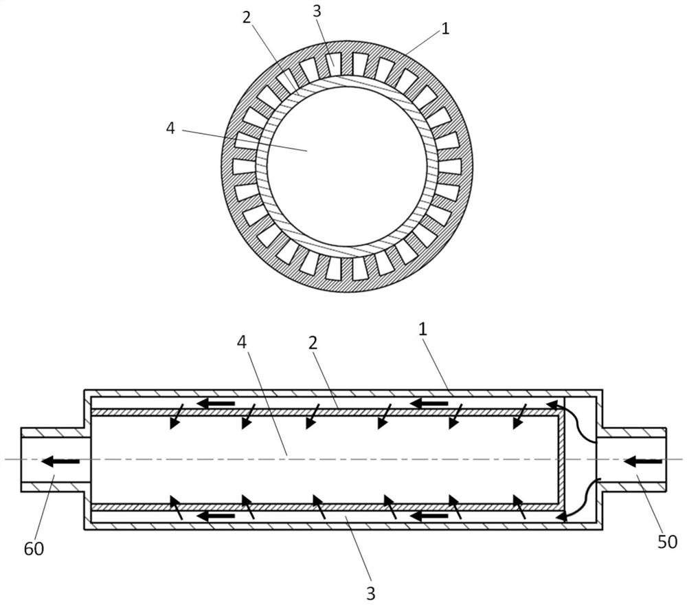
[0037] As shown in Figure 1, Figure 3 to Figure 6, a pump-driven two-phase fluid circuit evaporator provided according to the present invention. for

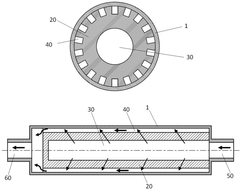
[0038] The design of a conventional two-phase fluid loop cylindrical evaporator is shown in Figure 2. The evaporator uses a hydrophilic reverse

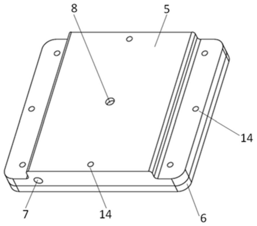
[0039] Further, for the specific implementation example of the flat plate evaporator, as shown in FIG. 3 and FIG. 4 . Its structure includes: top cover

[0040] Further, it also includes: a slit 12; the slit 12 communicates with the liquid flow channel through hole 7. under the slit 12

[0042] The specific embodiments of the present invention have been described above. It should be understood that the present invention is not limited to the above


PUM


Abstract

The present invention provides a pump-driven two-phase fluid circuit evaporator, comprising: an evaporator shell 1, a hydrophobic capillary core 2, an axial liquid channel 3 and an axial steam main channel 4; the hydrophobic capillary core 2 is installed Inside the evaporator shell 1; a plurality of axial liquid channels 3 are arranged between the evaporator shell 1 and the hydrophobic capillary core 2; internal. For the two-phase fluid circuit driven by the capillary pump, the present invention uses hydrophobic porous materials to cover the surface of the open micro channels of the evaporator, so that the liquid cannot occupy the space of the main steam channel due to condensation under various orientations or the influence of gravity. The steam bubbles that may exist in the liquid channel can be smoothly overflowed from the channel, which is beneficial to the smooth start of the evaporator and the reduction of the superheat at the start, and improves the heat transfer coefficient of the evaporation process.

Description

Pump Driven Two-Phase Fluid Loop Evaporator technical field [0001] The present invention relates to the technical field of heat transfer elements, in particular, to a pump-driven two-phase fluid circuit evaporator. Background technique At present, many two-phase fluid circuit designs adopt evaporative heat sinks, such as loop heat pipes, capillary suction loops, mechanical Mechanical pump-assisted loop heat pipe or capillary suction loop, or purely mechanical pump-driven, gas-liquid separation two-phase fluid loop, etc. Tradition As disclosed in the patent document CN107529365B, a gravity-assisted multi-evaporator two-phase fluid circuit device includes a Thin evaporator, vapor pipeline, condenser pipeline, liquid pipeline, liquid accumulator, it also includes vapor concentrator, inverted U-shaped pipe fittings, 3 to 12 capillary evaporators are used for loop valves, liquid input pipelines, liquid flow dividers, and are evenly arranged on the heat source to condense...

Claims


Application Information

Patent Timeline
Patent Type & Authority Patents(China)
IPC IPC(8): F28D15/04
CPCF28D15/043
Inventor 李志松姜建飞牟旭娜申军烽许忠林
Owner SHANGHAI SATELLITE ENG INST
Why Eureka
Try Eureka