Supercharge Your Innovation With Domain-Expert AI Agents!

Natural gas sand detection device

A detection device, natural gas technology, applied in the direction of measuring devices, instruments, scientific instruments, etc., can solve the problems of easy deviation of detection results, inaccurate results, corrosion of detection devices, etc.

Active Publication Date: 2020-12-08
北京燃气房山有限责任公司
View PDF1 Cites 0 Cited by
  • Summary
  • Abstract
  • Description
  • Claims
  • Application Information

AI Technical Summary

Problems solved by technology

[0007] However, the device rotates the rotating body outside the detection pipeline, and cannot accurately rotate it to the center position of the detection flow channel, so the rays cannot be accurately corresponded to the amplifiers one by one, and the detection results are prone to deviations. At the same time, the detection pipeline does not detect When the rotating body rotates to the other direction, although it does not affect the fluid flow direction, the detection device has been placed in the natural gas transportation pipeline for a long time, which will corrode the detection device in the long run, resulting in inaccurate results

Method used


Image

  • Natural gas sand detection device
  • Natural gas sand detection device
  • Natural gas sand detection device

Examples


Embodiment 1

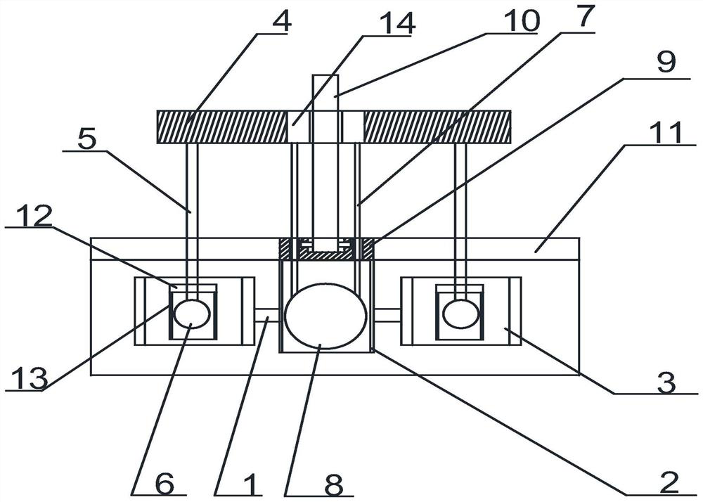
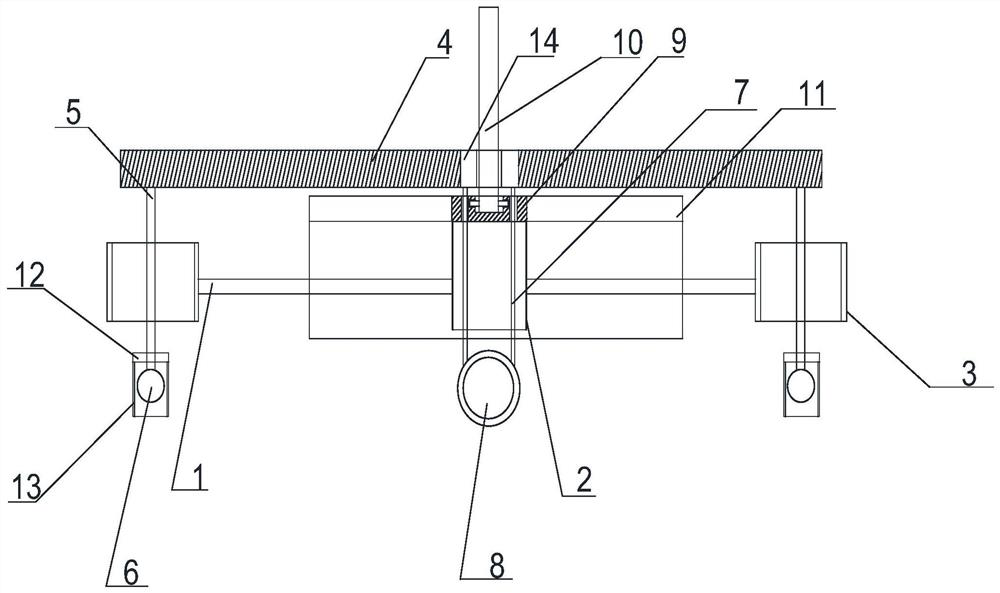
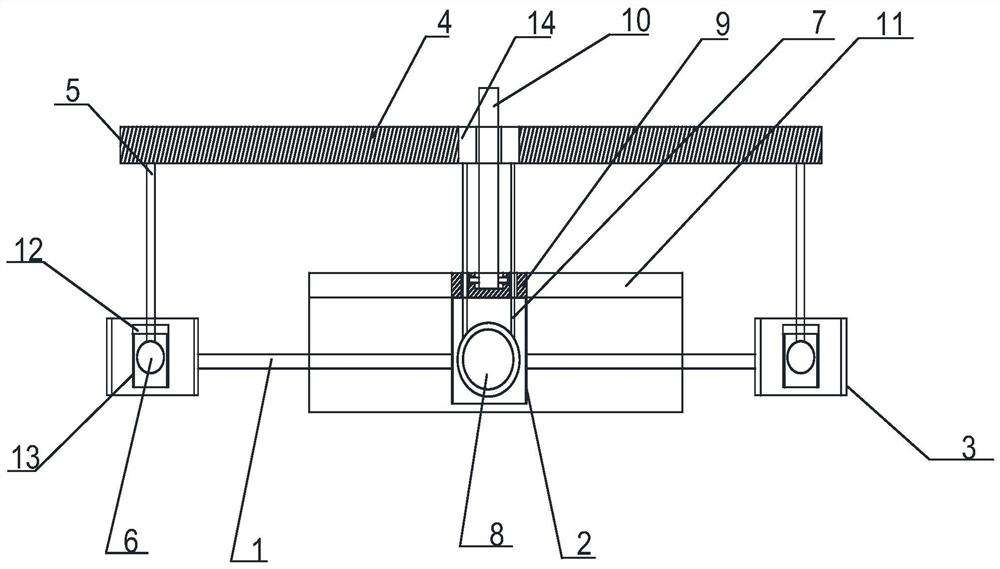
[0048] Such as figure 1 with 4 As shown, the device includes six first telescopic rods 1 and six second telescopic rods 4, one end of the first telescopic rods 1 is connected to the side of the first fixed cylinder 2 with the lower end open, and the other end is connected to the lower end open respectively. The side of the second fixed cylinder 3 is connected, and the first telescopic rod 1 is evenly distributed on the plane where the cross section of the first fixed cylinder 2 is located. After the first telescopic rod 1 is stretched, its structure is as follows: Figure 5 As shown; the second fixed cylinder 3 is fixed on the inner wall of the detection pipeline by the telescopic support of the first telescopic rod 1;

[0049] The upper end of the first fixed cylinder 2 passes through the rotating shaft and an end of the adjustment rod 10, the third fixed cylinder 14 is threaded on the adjustment rod 10, one end of the second telescopic rod 4 is connected with the side of th...

Embodiment 2

[0057] On the basis of Embodiment 1, the first connecting rod 5 is provided with two mutually perpendicular fixed rods 15, and the upper end of the second fixed cylinder 3 is provided with a groove 16 corresponding to the fixed rods 15. The structure is as follows: Figure 7 As shown, when the distance between the first telescopic rod 1 and the second telescopic rod 4 is shortened, the second telescopic rod 4 drives the first connecting rod to move downward, and the fixed rod 15 is snapped into the groove 16 from above the groove 16 , the structure is as Figure 8 As shown, after the first telescopic rod is stretched and stretched, when the first telescopic rod is required to drive the second telescopic rod to stretch, under the action of the fixed rod, the first connecting rod can be used to drive the second telescopic rod to stretch together, further improving Use efficiency.

[0058] At the same time, if Figure 8 As shown, the first connecting rod 5 is covered with a pro...

Embodiment 3

[0060] Such as Figure 4 , 5 , 7, 8 and Figure 9 As shown, a protective shell 17 is also provided on the upper end of the first fixed cylinder 2, the upper end of the first fixed cylinder 2 is connected with a connecting plate 9, the upper end of the connecting plate 9 is provided with a connecting groove, and the inner wall of the connecting groove is provided with a ring-shaped Groove, the side of the lower end of the adjustment rod 10 is provided with an annular projection, which corresponds to the annular groove, and then the adjustment rod is connected to the connecting plate 9 through the annular projection, and can rotate on the connecting plate 9. Such as Figure 8 with 9 As shown, the protective case 17 includes an upper plate 11 and two parallel side plates, the upper plate 11 is provided with a slot, the first connecting rod passes through the slot and slides along the slot when the first telescopic rod stretches, wherein When the first telescopic rod 1 is shor...


PUM


Abstract

The invention discloses a natural gas sand content detection device. The sand content of natural gas in a pipe is detected through a gamma ray source, an amplifier and a scintillation probe; the device is fixed to the inner wall of a detection pipe through stretching and retracting of a first telescopic rod, and when detection needs to be conducted, the distance between the first telescopic rod and the second telescopic rod is adjusted, so the ray receiving device at the lower end of the first connecting rod and the ray emitting device at the lower end of the second connecting rod are locatedat the lower end of the second fixing cylinder and the lower end of the first fixing cylinder correspondingly. When the device is in use, no matter what angle the first telescopic rod is fixed on theinner wall of the detection pipe, the ray beams emitted by the ray receiving device and the ray beams emitted by the ray receiving and emitting device can always correspond to each other one by one, so gravel detection errors generated when the detection device is placed and adjusted and the first telescopic rod is not perpendicular to the inner wall of the detection pipeline can be effectively prevented.

Description

technical field [0001] The invention relates to a detection device, in particular to a detection device for sand content in natural gas. Background technique [0002] Natural gas plays a key role in the development of a country and the progress of industrial technology. Due to its environmental protection and high-quality features, natural gas has become the main energy source in the 21st century. [0003] Natural oil and gas resources are mainly located in unconsolidated sandstone formations, whose rocks have weak cementation and shallow burial, so sand production is very easy to occur when affected by fluid drag and pressure reduction. Natural gas sand production will not only reduce the production of gas wells and fields, but also damage downhole casings and surface equipment, affecting gathering and transportation systems and environmental resources. [0004] The safety of natural gas production has been plagued by sand production, and people are paying more and more a...

Claims


Application Information

Patent Timeline
Patent Type & Authority Patents(China)
IPC IPC(8): G01N23/02
CPCG01N23/02G01N2223/03G01N2223/1013G01N2223/308G01N2223/316G01N2223/505G01N2223/638G01N2223/652
Inventor 高友华
Owner 北京燃气房山有限责任公司
Features
  • R&D
  • Intellectual Property
  • Life Sciences
  • Materials
  • Tech Scout
  • Unparalleled Data Quality
  • Higher Quality Content
  • 60% Fewer Hallucinations
Learn More