Steel tube clamping device for machining

A clamping device and machining technology, applied in the field of machining, can solve the problems of troublesome operation, limited size of the curved plate, low work efficiency, etc., and achieve the effects of convenient machining, strong adaptability and simple operation

Inactive Publication Date: 2020-08-11
瑞安市祥泽机械设备经营部
View PDF8 Cites 0 Cited by
  • Summary
  • Abstract
  • Description
  • Claims
  • Application Information

AI Technical Summary

Problems solved by technology

[0003] In the process of steel pipe processing, it is necessary to clamp and fix the steel pipe. The existing devices generally use a fixed-shaped arc-shaped plate and adjust multiple screws to drive the

Method used


Image

  • Steel tube clamping device for machining
  • Steel tube clamping device for machining
  • Steel tube clamping device for machining

Examples


Embodiment 1

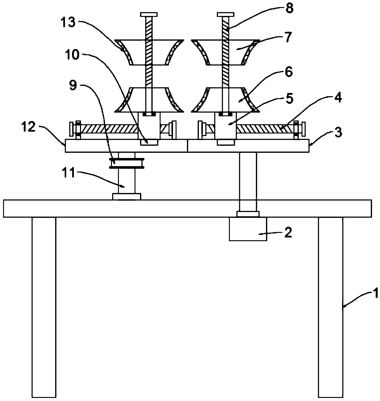
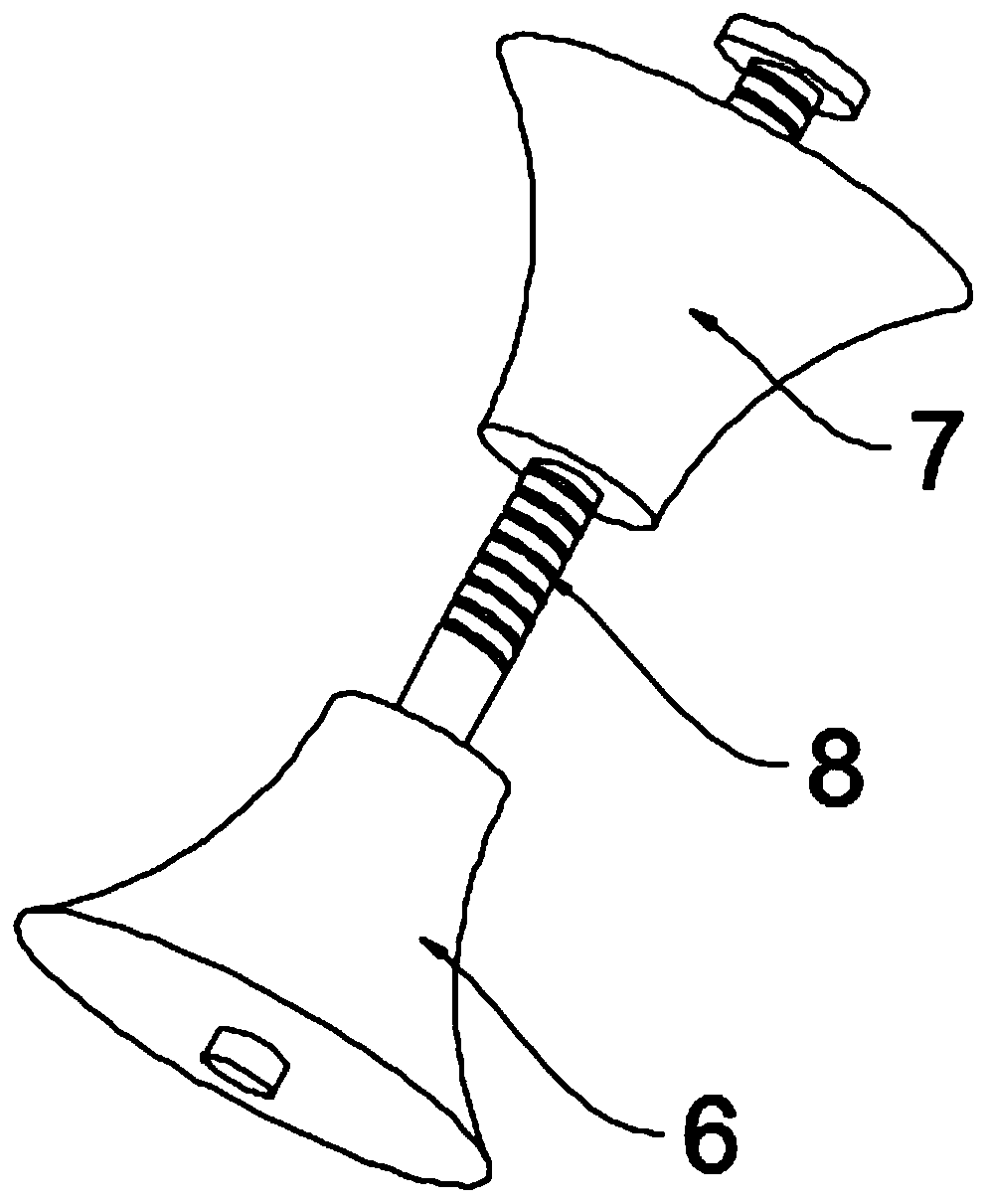
[0023] see Figure 1~2 , in an embodiment of the present invention, a steel pipe clamping device for mechanical processing includes at least two sets of clamping assemblies longitudinally installed on the frame 1, and the clamping assemblies include a first gear 3, a second gear 12, an upper The clamping platform 7 and the lower clamping platform 6, the first gear 3 and the second gear 12 are installed on the frame 1 through the installation shaft 11 and the bearing rotation respectively, the first gear 3 meshes with the second gear 12, and the The upper surfaces of the first gear 3 and the second gear 12 are all rotatably equipped with first threaded rods 4. In this embodiment, both sides of the upper surfaces of the first gear 3 and the second gear 12 are fixed with fixed plates. The rod 4 is rotationally connected with the fixed plate through a bearing, and a first handle is fixed at one end of the first threaded rod 4. In this embodiment, the first handle is preferably fix...

Embodiment 2

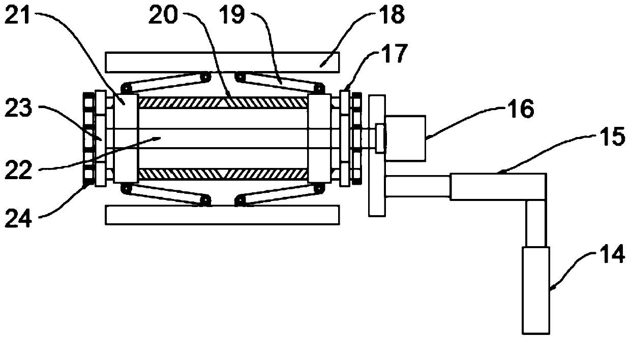
[0025] see image 3 The difference between the embodiment of the present invention and embodiment 1 is that due to the different thickness of the pipe wall of the steel pipe, when the pipe wall of the steel pipe is relatively thin, the deformation of the steel pipe may be caused during clamping, thus, a protection unit is also included , the protection unit includes a protection assembly and an adjustment assembly for adjusting the position of the protection assembly, the adjustment assembly includes a first electric push rod 14 and a second electric push rod 15, the first electric push rod 14 is fixedly installed on the frame, the second Two electric push rods 15 are fixed on the telescopic rod top of the first electric push rod 14, and the protection assembly includes a second motor 16, a rotating shaft 22, a driving gear 23, a driven gear 17, a two-way screw rod 20, a movable plate 21, and a connecting rod 19 and arc-shaped plate 18, the second motor 16 is fixedly mounted o...


PUM


Abstract

The invention discloses a steel tube clamping device for machining, and relates to the technical field of machining. The problems of complex operation and low working efficiency of an existing steel tube clamping device are mainly solved. The steel tube clamping device comprises at least two groups of clamping assemblies longitudinally installed on a machine frame, and the clamping assemblies comprise first gears, second gears, upper clamping tables and lower clamping tables; the steel tube clamping device further comprises a protective unit, the protective unit comprises a protective assemblyand an adjusting assembly for adjusting the position of the protective assembly, and the protective assembly comprises a second motor, a rotary shaft, a driving gear, a driven gear, a two-way screw,a movable plate, a connecting rod and an arc plate. The clamping assemblies are arranged, the operation is simple, convenient and fast, the clamping assemblies can adapt to steel tubes with differentdiameters, and the adaptability is high; and the protective unit is arranged to protect the steel tubes from deforming, the protective assembly can drive the steel tubes to rotate, and the machining is convenient.

Description

technical field [0001] The invention relates to the technical field of mechanical processing, in particular to a steel pipe clamping device for mechanical processing. Background technique [0002] Machining refers to the process of changing the shape, size or performance of a workpiece through a mechanical device; in the production process, any process of changing the shape, size, position and nature of the production object to make it a finished or semi-finished product is called crafting process. The process can be divided into casting, forging, stamping, welding, machining, assembly and other processes. The mechanical manufacturing process generally refers to the sum of the machining process of parts and the assembly process of machines. Other processes are called auxiliary processes. process. [0003] In the process of steel pipe processing, it is necessary to clamp and fix the steel pipe. The existing devices generally use a fixed-shaped arc-shaped plate and adjust mu...

Claims


Application Information

Patent Timeline
IPC IPC(8): B25B11/00
CPCB25B11/00
Inventor 不公告发明人
Owner 瑞安市祥泽机械设备经营部
Why Eureka
Try Eureka