Layout and control method of tilting rotor-wing vertical take-off and landing aircraft

A technology of vertical take-off and landing and tilt-rotor, applied in the aviation field, can solve problems such as insufficient lift and rudder effect, airflow interference between rotor and wing, complicated control, etc., so as to reduce airflow interference and control difficulty, reduce burden and Control difficulty and solve the complex effects of flight control

Inactive Publication Date: 2020-08-11
BEIHANG UNIV
View PDF5 Cites 14 Cited by
  • Summary
  • Abstract
  • Description
  • Claims
  • Application Information

AI Technical Summary

Problems solved by technology

During the vertical take-off and landing phase of the first two vertical take-off and landing aircrafts, the upper surface of the wing is perpendicular to the direction of incoming flow, and the windward area is too large, which will generate a large pressure difference resistance
In the second type of tiltrotor, because the rotor is just above the wing during the vertical take-off and landing phase, the slipstream from the rotor will directly act on the upper surface of the wing, which will generate turbulent flow and affect the control of the aircraft.
The third type of vertical take-off and landing aircraft uses a large amount of power to drive and control the main rotor, but the main rotor is not the main source of lift during high-speed flight, and its design is limited by the shape of traditional helicopters, and the dead weight of the structure is too large
However, in the process of mode conversion from vertical take-off and landing to level flight, there are problems of poor aerodynamic condition of the wing, insufficient lift and rudder effect, resulting in the underutilization of the wing
At the same time, this also requires the power system not only to have sufficient margin to provide control force, but also to ensure sufficient vertical power components to offset the aircraft's own gravity during the tilting process, which seriously aggravates the burden on the power system
[0005] In summary, the existing vertical take-off and landing aircraft has large resistance during the vertical take-off and landing phase, serious airflow interference between the rotor and the wing, complex control, poor aerodynamic conditions of the wing during the transition between vertical take-off and landing and level flight, and low utilization efficiency , heavy burden on the power system, and complex control problems, it is necessary to reduce the airflow interference between the rotor and the wing during the vertical take-off and landing stage, and to lift the aircraft.

Method used


Image

  • Layout and control method of tilting rotor-wing vertical take-off and landing aircraft
  • Layout and control method of tilting rotor-wing vertical take-off and landing aircraft
  • Layout and control method of tilting rotor-wing vertical take-off and landing aircraft

Examples


Embodiment Construction

[0038] The present invention will be further described below in conjunction with the drawings. These drawings are simplified schematic diagrams, which merely illustrate the basic structure of the present invention in a schematic manner.

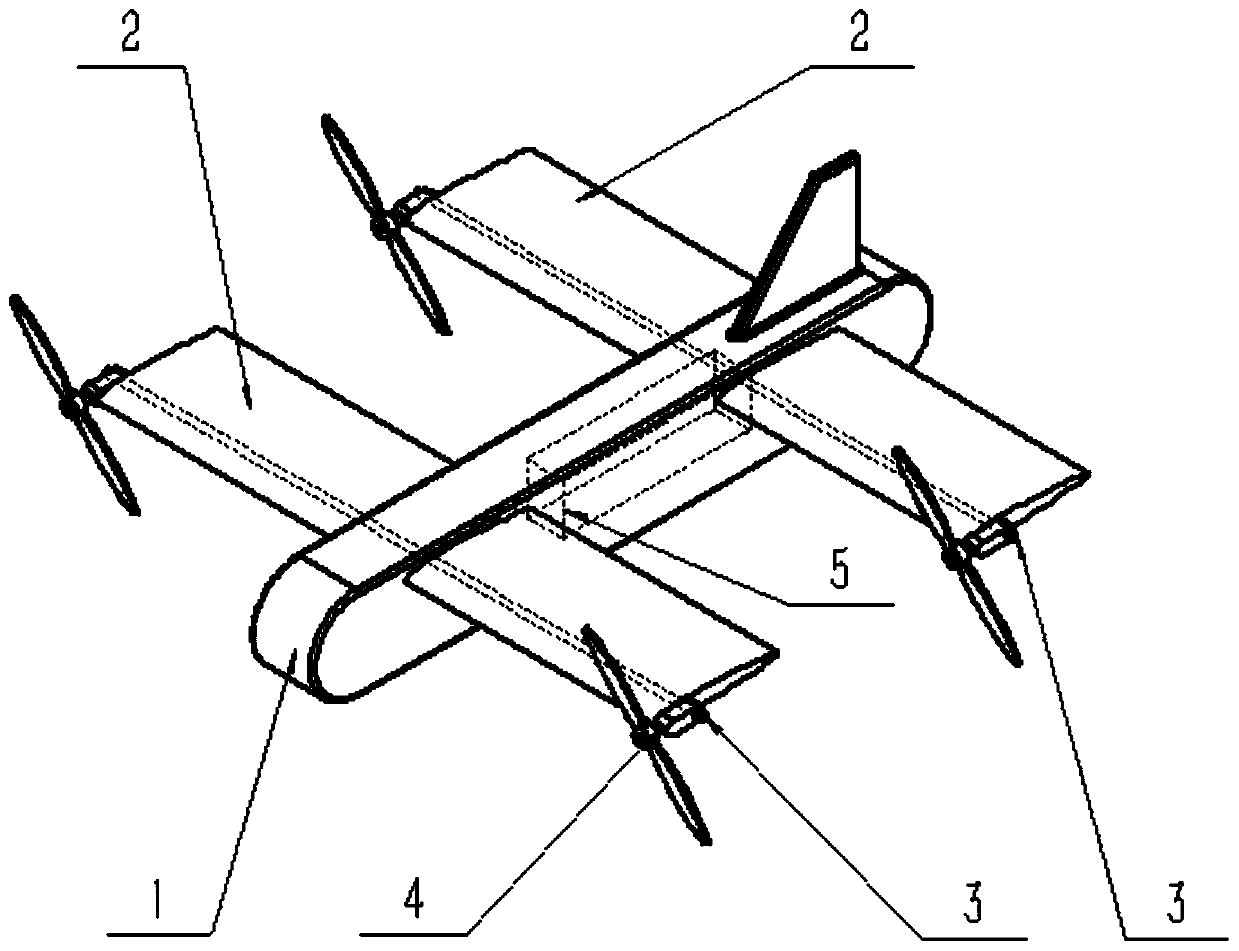
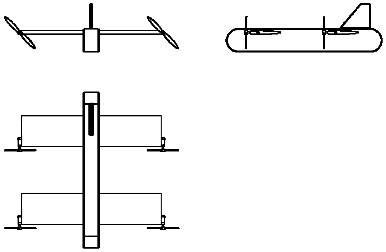
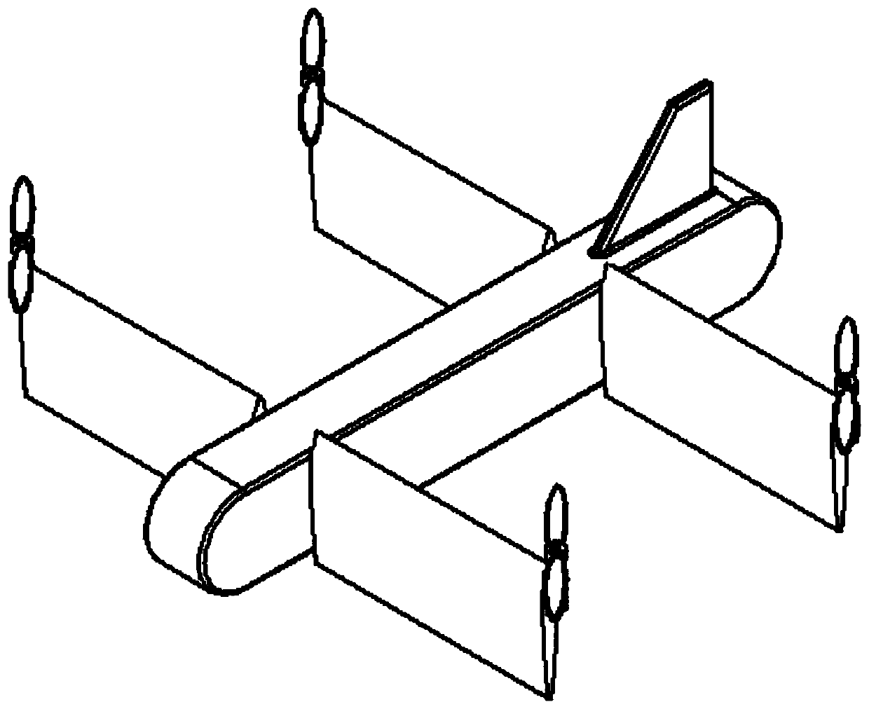
[0039] A tilt-rotor-wing vertical take-off and landing aircraft layout, such as figure 1 , figure 2 As shown, it includes: a fuselage 1, a wing 2, a rotating shaft 3, a rotor 4, and an electronic device 5.

[0040] The fuselage 1 is the main part of the airplane, used to bear the payload and connect the other parts of the airplane.

[0041] The wing 2 is divided into two groups, front and rear, which are connected to the fuselage 1 through two rotating shafts 3 arranged at the front and rear of the fuselage 1, and can rotate around the corresponding rotating shaft in the range of 0° to 90° for use in level flight mode To generate lift. An aerodynamic rudder surface is provided on the wing 2 to provide the control force of the aircraft in each mod...


PUM


Abstract

The invention relates to a layout and control method of a tilting rotor-wing vertical take-off and landing aircraft. Tandem wing layout is adopted; the wing tips of two sides of front wings and rear wings are each provided with one set of rotor wings, and altogether, four sets of rotor wings are adopted, so that a power system can be formed; the wings and the rotor wings can rotate around rotatingshafts penetrating through the interiors of the wings within a certain angle range, so that the respective tilting of the rotor wings and the wings is achieved. According to the control method, the vertical take-off and landing and high-speed level flight of the aircraft can be achieved; the angles of the rotor wings and the wings can be properly adjusted in all stages of flight, and the overallefficiency of the aircraft is optimized; the rotor wings and the wings can tilt respectively, resistance is small in vertical take-off and landing stages, and airflow interference between the rotor wings and the wings is small; when the aircraft is switched between a vertical take-off mode and a landing mode, the utilization efficiency of the wings is high, the burden of the power system is low; and flight control over a whole flight process is simple. The vertical take-off and landing aircraft has a wide application prospect.

Description

Technical field [0001] The present invention relates to a layout and control method of a tilt-rotor-wing vertical take-off and landing aircraft, in particular to a layout and control method of a vertical take-off and landing aircraft in which the rotor and the wing can be tilted separately, belonging to the field of aviation technology. Background technique [0002] Vertical take-off and landing aircraft can not only take off and land vertically like a helicopter, without being restricted by the runway, but also can fly horizontally at high speed like a fixed-wing aircraft. It combines the advantages of both fixed-wing aircraft and helicopters. It has a very broad field of civilian and military applications. Application prospects. [0003] At present, there are mainly the following types of vertical take-off and landing aircraft. The first type is a vertical take-off and landing fighter represented by "AV-8B" and "F-35" that uses lift fans or vector nozzles to provide vertical tak...

Claims


Application Information

Patent Timeline
Patent Type & Authority Applications(China)
IPC IPC(8): B64C29/00B64C27/28B64C27/52B64C3/38
CPCB64C3/385B64C27/28B64C27/52B64C29/00
Inventor 周尧明胡鑫苏雨潘风行
Owner BEIHANG UNIV
Why Eureka
Try Eureka