Novel plate chain bucket elevator

A bucket elevator, plate chain technology, applied in the direction of conveyor, transportation and packaging, can solve the problems of high load-bearing performance requirements of the plate chain, shortened service life of the plate chain, and the structure is not compact enough to achieve stable relative position, The effect of extended service life and large load capacity

Active Publication Date: 2020-08-11
ZHEJIANG BOYU ELECTROMECHANICAL
View PDF9 Cites 0 Cited by
  • Summary
  • Abstract
  • Description
  • Claims
  • Application Information

AI Technical Summary

Problems solved by technology

[0006] In this high-speed plate chain bucket elevator, the driving wheel used is toothless, and the friction between the wheel surface of the driving wheel and the inner arc concave surface of the inner chain plate is used to drive the plate chain to run; the plate chain bucket elevator The disadvantages are: (1) Affected by the size of the hopper, the distance between adjacent inner chain plates is relatively large. At the same time point, there are fewer contact points between the inner chain plate and the driving wheel. Insufficient strength, which makes the board chain prone to slipping during operation; (2) the board chain is assembled on the back of the hopper, and only one board chain is installed on the back of the hopper, which not only requires high load-bearing performance of the board chain, As a result, the service life of the plate chain is shortened, and the hopper protrudes outside the plate chain, resulting in a larger overall volume of the equipment and a less compact structure

Method used


Image

  • Novel plate chain bucket elevator
  • Novel plate chain bucket elevator
  • Novel plate chain bucket elevator

Examples


Embodiment 1

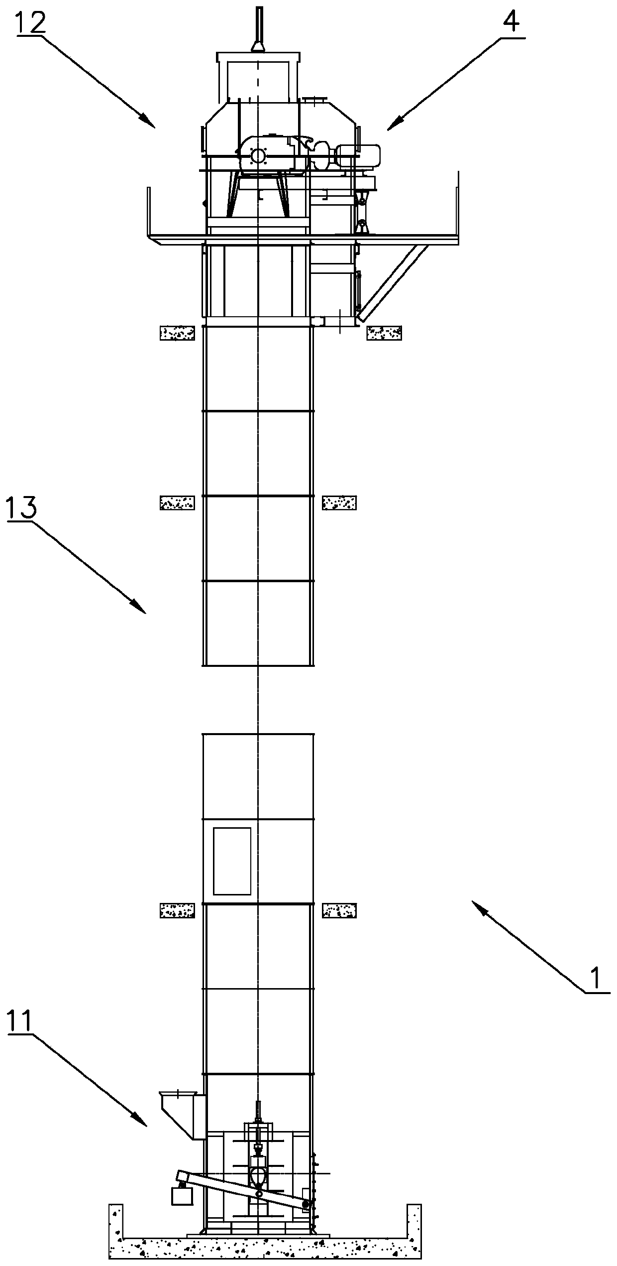
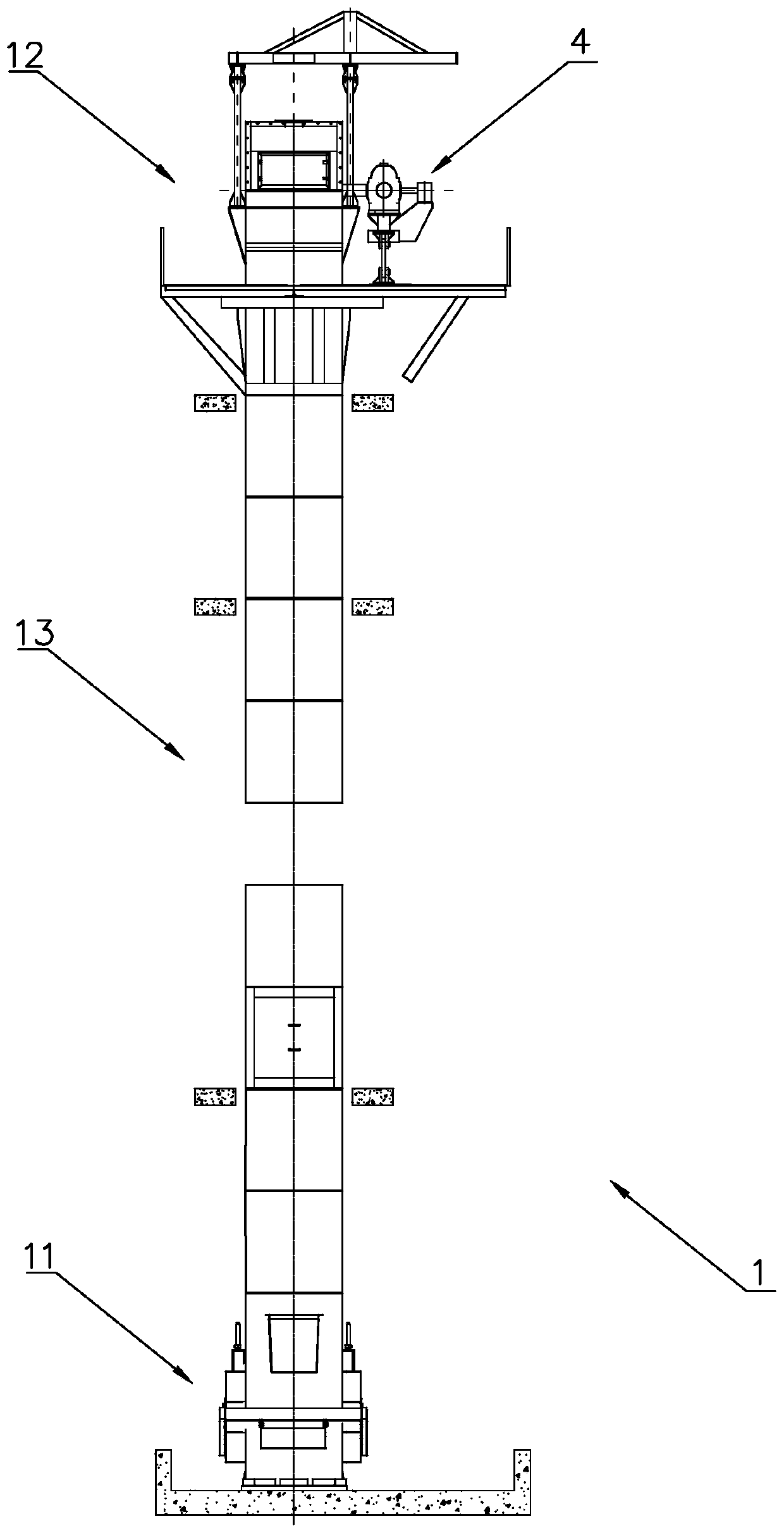
[0036] Such as figure 1 , figure 2 and Figure 4 As shown, a novel plate chain bucket elevator in this embodiment includes a housing 1, and the housing 1 includes a lower section 11, an upper section 12 directly above the lower section 11, and a connecting lower section 11. and several intermediate casing segments 13 of the upper section 12, the number of intermediate casing segments 13 can be set according to specific lifting height needs.

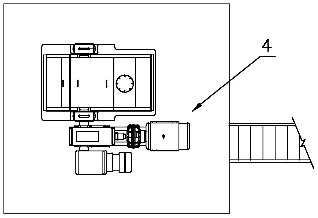
[0037] Wherein, the upper section 12 of the housing 1 is rotatably connected with the driving shaft 2, and the driving shaft 2 is fixedly provided with two driving wheels 3, and the driving wheel 3 adopted in this embodiment is gearless; the top of the housing 1 is provided with There is a drive mechanism 4 for driving the drive shaft 2 and the drive wheel 3 to rotate such as image 3 .

[0038] And then rotatably connected with driven shaft 5 in the lower section 11 of housing 1, two hoisting wheels 6 are fixedly arranged on this dr...


PUM

PropertyMeasurementUnit
Angleaaaaaaaaaa

Abstract

The invention discloses a novel plate chain bucket elevator. The elevator comprises a shell, wherein two pairs of driving wheels and lifting wheels are arranged in the shell; a lifting chain is connected between the driving wheel and the lifting wheel which belong to the same pair in a closed manner; the driving wheels and the lifting wheels are gearless; each lifting chain comprises a plurality of chain links which are hinged with one another through a connecting structure; each chain link comprises two inner chain plates which are arranged oppositely and at least two connecting pipes which are fixedly connected with the two inner chain plates; the surfaces of the connecting pipes are in friction fit with the wheel surfaces of the driving wheels or the lifting wheels; and a hopper which is positioned between the two lifting chains is fixedly arranged on the connecting structure. Because the number of the connecting pipes in the lifting chains is large, and the distance between the connecting pipes is controllable, large friction force can be generated between the lifting chains and the driving wheels, and the lifting chains cannot slip in the running process. Meanwhile, the hopperis arranged between the two lifting chains, so that the equipment is compact in structure and small in size.

Description

technical field [0001] The invention belongs to the technical field of elevators, and in particular relates to a novel plate chain bucket elevator. Background technique [0002] The plate chain bucket elevator is suitable for vertically conveying powdery, granular, and block materials, and can also lift materials with high abrasiveness, such as fly ash, slag, limestone, cement raw meal, cement clinker, cement, Coal, dry clay, etc., the lifting height can reach up to 40m. [0003] The traditional plate chain bucket elevator usually includes a shell, in which a toothed drive wheel and a toothed lifting wheel are arranged, and a sleeve roller chain is closed and connected between the toothed drive wheel and the toothed lifting wheel, and the sleeve The hopper is fixedly installed on the roller chain; through the meshing transmission of the sleeve roller chain with the toothed drive wheel and the toothed lifting wheel, the hopper conveys materials in a circular motion up and do...

Claims


Application Information

Patent Timeline
IPC IPC(8): B65G17/12B65G17/36
CPCB65G17/12B65G17/36
Inventor 朱桂芳傅关钱王旭高君王文卿
Owner ZHEJIANG BOYU ELECTROMECHANICAL
Why Eureka
Try Eureka